

URDF in ROS 2: Describe a Robot Model with Links and Joints
Learn URDF in ROS 2 Jazzy: links, joints, origins and inertia, a xacro model of a two-wheel robot, robot_state_publisher, RViz and numpy transform maths.
Think of the assembly sheet that comes with a flat-pack study table from a furniture shop on AB Road. It lists every part: top panel, two side panels, a drawer.
Then it says exactly how each part attaches to the one before it: "fix side panel B 4 cm from the edge of the top", "the drawer slides along rail C".
Nobody needs a photo of the finished table to build it. The parts list and the attachment rules are enough, and anyone holding the sheet ends up with the same table.
A robot description works the same way. It names each rigid part, says where it is bolted on, and says whether that connection is rigid, spins or slides.
What is URDF in ROS 2?
Map the assembly sheet onto a robot. Each panel is a link, a rigid body such as the chassis, a wheel or a lidar. Each attachment rule is a joint, which names a parent link, a child link, the offset between them and how the child may move.
The "4 cm from the edge" is the joint's origin. A drawer sliding on a rail is a prismatic joint, and a wheel on an axle is a continuous joint.
URDF is an XML file format used in ROS to describe a robot's physical structure as a tree of links joined by joints, including each part's shape, collision geometry, mass and how it moves.
RViz draws the robot from this one file, robot_state_publisher computes frames from it, Gazebo simulates it, and Nav2 uses those frames to know where the lidar sits. A wrong URDF misleads all of them.
This lesson describes a small two-wheeled robot, the kind in differential drive robots, inside the workspace from installing ROS 2. It targets ROS 2 Jazzy; the files work unchanged on Lyrical.
Links and joints: the robot as a tree
A URDF must form a tree: one root link, and every other link has exactly one parent. Loops, such as a four-bar linkage, cannot be described directly.
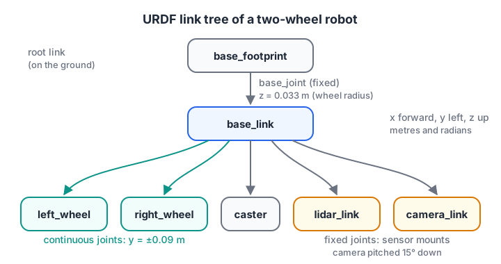
Every arrow is a joint. Only the two wheel joints move; the rest are fixed mounts.
The REP 105 convention for mobile robots puts base_link on the robot body and base_footprint directly below it on the ground. Nav2 and many drivers expect these names, so use them.
Joint types you will use
| Joint type | Motion | Limits needed? | Example |
|---|---|---|---|
| fixed | None, rigid mount | No | Lidar bolted to the chassis |
| continuous | Unlimited rotation about an axis | No | Drive wheel |
| revolute | Rotation between a lower and upper angle | Yes | Servo joint in an arm |
| prismatic | Sliding along an axis | Yes | Linear actuator, lift |
| floating, planar | 6 or 3 degrees of freedom | No | Rare in practice |
ROS conventions from REP 103 apply throughout: lengths in metres, angles in radians, and for the robot body, x points forward, y left and z up.
What goes inside a link
A link can have three optional blocks, and beginners mix them up.
- visual: what RViz and Gazebo draw. It can be a mesh file.
- collision: the shape used for contact. Keep it simple, a box or cylinder, so physics stays fast.
- inertial: mass and the 3×3 inertia tensor. Without it, Gazebo ignores the link or behaves strangely.
Here is a minimal, valid URDF with the body and one wheel. Read it top to bottom once; xacro will shorten it later.
<?xml version="1.0"?>
<robot name="my_robot">
  <link name="base_footprint"/>

  <link name="base_link">
    <visual>
      <geometry><box size="0.20 0.14 0.06"/></geometry>
      <material name="blue"><color rgba="0.15 0.39 0.92 1.0"/></material>
    </visual>
    <collision>
      <geometry><box size="0.20 0.14 0.06"/></geometry>
    </collision>
    <inertial>
      <mass value="1.2"/>
      <inertia ixx="0.00232" ixy="0" ixz="0" iyy="0.00436" iyz="0" izz="0.00596"/>
    </inertial>
  </link>

  <joint name="base_joint" type="fixed">
    <parent link="base_footprint"/>
    <child link="base_link"/>
    <origin xyz="0 0 0.033" rpy="0 0 0"/>
  </joint>

  <link name="left_wheel">
    <visual>
      <geometry><cylinder radius="0.033" length="0.026"/></geometry>
    </visual>
    <collision>
      <geometry><cylinder radius="0.033" length="0.026"/></geometry>
    </collision>
    <inertial>
      <mass value="0.05"/>
      <inertia ixx="0.0000164" ixy="0" ixz="0" iyy="0.0000164" iyz="0" izz="0.0000272"/>
    </inertial>
  </link>

  <joint name="left_wheel_joint" type="continuous">
    <parent link="base_link"/>
    <child link="left_wheel"/>
    <origin xyz="0 0.09 0" rpy="-1.5708 0 0"/>
    <axis xyz="0 0 1"/>
  </joint>
</robot>
A cylinder's length runs along its own z axis. The joint origin rolls the wheel −90 degrees about x, so its z axis points left, and <axis xyz="0 0 1"/> spins it like an axle. Positive joint velocity then drives the robot forward.
Quick check
Which joint type should a drive wheel use in URDF?
A drive wheel turns without limits, which is a continuous joint. Revolute needs lower and upper limits.
How does a URDF become coordinate frames?
Each joint's origin is a transform: a translation xyz and a rotation rpy (roll about x, pitch about y, yaw about z, applied in that order about fixed axes). Chaining transforms from the root to any link tells you where that link is.
That is forward kinematics, as in robot kinematics, written in XML. This block chains the 4×4 matrices for a camera tilted 15 degrees down and finds where a point it sees lands in the ground frame.
import numpy as np

def rpy_matrix(r, p, y):                       # URDF: R = Rz(yaw) @ Ry(pitch) @ Rx(roll)
    cr, sr, cp, sp, cy, sy = np.cos(r), np.sin(r), np.cos(p), np.sin(p), np.cos(y), np.sin(y)
    Rx = np.array([[1, 0, 0], [0, cr, -sr], [0, sr, cr]])
    Ry = np.array([[cp, 0, sp], [0, 1, 0], [-sp, 0, cp]])
    Rz = np.array([[cy, -sy, 0], [sy, cy, 0], [0, 0, 1]])
    return Rz @ Ry @ Rx

def joint_tf(xyz, rpy):
    T = np.eye(4)
    T[:3, :3], T[:3, 3] = rpy_matrix(*rpy), xyz
    return T

T_foot_base = joint_tf([0, 0, 0.033], [0, 0, 0])           # base_joint
T_base_cam = joint_tf([0.10, 0, 0.05], [0, np.radians(15), 0])  # camera_joint, pitched down
T_foot_cam = T_foot_base @ T_base_cam                       # chain the joints

np.set_printoptions(precision=3, suppress=True)
print("camera origin in base_footprint:", T_foot_cam[:3, 3])
p_cam = np.array([0.3, 0.0, 0.0, 1.0])        # a point 0.3 m straight ahead of the lens
p_foot = T_foot_cam @ p_cam
print("that point in base_footprint:   ", p_foot[:3])
print("lens is", round(T_foot_cam[2, 3] / np.tan(np.radians(15)), 3),
      "m behind where its centre ray hits the floor")
The point 0.3 m along the camera's view ends up 0.39 m ahead of the robot and only 5 mm above the floor, so the image centre looks at the floor about 0.31 m ahead of the lens. Had the URDF said 0 degrees, every detected obstacle would float at lens height. A careless rpy breaks perception.
Check a URDF tree like check_urdf does
The check_urdf tool from the liburdfdom-tools package parses a file and prints its tree. This block does the same checks on a URDF string: one root, every child with one parent, and every joint naming real links.
import xml.etree.ElementTree as ET

urdf = """<robot name="my_robot">
  <link name="base_footprint"/><link name="base_link"/><link name="left_wheel"/>
  <link name="right_wheel"/><link name="caster"/><link name="lidar_link"/><link name="camera_link"/>
  <joint name="base_joint" type="fixed"><parent link="base_footprint"/><child link="base_link"/></joint>
  <joint name="left_wheel_joint" type="continuous"><parent link="base_link"/><child link="left_wheel"/></joint>
  <joint name="right_wheel_joint" type="continuous"><parent link="base_link"/><child link="right_wheel"/></joint>
  <joint name="caster_joint" type="fixed"><parent link="base_link"/><child link="caster"/></joint>
  <joint name="lidar_joint" type="fixed"><parent link="base_link"/><child link="lidar_link"/></joint>
  <joint name="camera_joint" type="fixed"><parent link="base_link"/><child link="camera_link"/></joint>
</robot>"""

root = ET.fromstring(urdf)
links = {l.get("name") for l in root.iter("link")}
children, parent_of = {}, {}
for j in root.iter("joint"):
    p, c = j.find("parent").get("link"), j.find("child").get("link")
    assert p in links and c in links, f"{j.get('name')} names a missing link"
    assert c not in parent_of, f"{c} has two parents"
    parent_of[c] = p
    children.setdefault(p, []).append((c, j.get("type")))
roots = links - set(parent_of)
print("robot name is:", root.get("name"), "| root link:", roots)
def show(link, depth=0):
    for child, jtype in children.get(link, []):
        print("    " * depth + f"└─ {child}  ({jtype})")
        show(child, depth + 1)
print(next(iter(roots)))
show(next(iter(roots)))
Change one joint's parent to a link name with a typo and the assertion fires, which is exactly the class of error check_urdf catches before RViz shows you a robot in pieces.
Cleaning up a URDF with xacro
Plain URDF repeats itself: two wheels differ only by side, and every inertia block is a hand calculation. xacro, an XML macro language, fixes this and outputs ordinary URDF.
Three features cover most robots:
<xacro:property name="wheel_r" value="0.033"/>defines a constant, used as${wheel_r}.${...}evaluates maths, such as${wheel_r * 2}or${pi/2}.<xacro:macro name="wheel" params="side y">defines a reusable block;<xacro:wheel side="left" y="1"/>expands it.
The inertia macros need the standard formulas for solid shapes. Computing them once in Python is a good check that the xacro maths is right.
def box_inertia(m, x, y, z):
    return m * (y**2 + z**2) / 12, m * (x**2 + z**2) / 12, m * (x**2 + y**2) / 12

def cylinder_inertia(m, r, h):                 # axis along the cylinder's own z
    side = m * (3 * r**2 + h**2) / 12
    return side, side, m * r**2 / 2

def sphere_inertia(m, r):
    i = 2 * m * r**2 / 5
    return i, i, i

parts = {
    "base_link (box 0.20x0.14x0.06, 1.2 kg)": box_inertia(1.2, 0.20, 0.14, 0.06),
    "wheel (r 0.033, h 0.026, 0.05 kg)": cylinder_inertia(0.05, 0.033, 0.026),
    "caster (sphere r 0.015, 0.01 kg)": sphere_inertia(0.01, 0.015),
}
for name, (ixx, iyy, izz) in parts.items():
    ok = ixx + iyy >= izz and iyy + izz >= ixx and ixx + izz >= iyy   # physical sanity
    print(f"{name:40} ixx={ixx:.7f} iyy={iyy:.7f} izz={izz:.7f}  valid={ok}")
The last column checks the triangle inequality that every real inertia tensor satisfies. Invented numbers often fail it, and Gazebo then makes the robot jitter or fly apart.
The full robot as a xacro file
Save this as urdf/my_robot.urdf.xacro in a package called my_robot_description. It describes the whole robot in the link tree above.
<?xml version="1.0"?>
<robot name="my_robot" xmlns:xacro="http://www.ros.org/wiki/xacro">
  <xacro:property name="base_x" value="0.20"/>
  <xacro:property name="base_y" value="0.14"/>
  <xacro:property name="base_z" value="0.06"/>
  <xacro:property name="wheel_r" value="0.033"/>
  <xacro:property name="wheel_w" value="0.026"/>
  <xacro:property name="wheel_sep" value="0.18"/>

  <xacro:macro name="box_inertia" params="m x y z">
    <inertial>
      <mass value="${m}"/>
      <inertia ixx="${m*(y*y+z*z)/12}" ixy="0" ixz="0"
               iyy="${m*(x*x+z*z)/12}" iyz="0" izz="${m*(x*x+y*y)/12}"/>
    </inertial>
  </xacro:macro>

  <xacro:macro name="cylinder_inertia" params="m r h">
    <inertial>
      <mass value="${m}"/>
      <inertia ixx="${m*(3*r*r+h*h)/12}" ixy="0" ixz="0"
               iyy="${m*(3*r*r+h*h)/12}" iyz="0" izz="${m*r*r/2}"/>
    </inertial>
  </xacro:macro>

  <link name="base_footprint"/>
  <link name="base_link">
    <visual><geometry><box size="${base_x} ${base_y} ${base_z}"/></geometry></visual>
    <collision><geometry><box size="${base_x} ${base_y} ${base_z}"/></geometry></collision>
    <xacro:box_inertia m="1.2" x="${base_x}" y="${base_y}" z="${base_z}"/>
  </link>
  <joint name="base_joint" type="fixed">
    <parent link="base_footprint"/><child link="base_link"/>
    <origin xyz="0 0 ${wheel_r}" rpy="0 0 0"/>
  </joint>

  <xacro:macro name="wheel" params="side reflect">
    <link name="${side}_wheel">
      <visual><geometry><cylinder radius="${wheel_r}" length="${wheel_w}"/></geometry></visual>
      <collision><geometry><cylinder radius="${wheel_r}" length="${wheel_w}"/></geometry></collision>
      <xacro:cylinder_inertia m="0.05" r="${wheel_r}" h="${wheel_w}"/>
    </link>
    <joint name="${side}_wheel_joint" type="continuous">
      <parent link="base_link"/><child link="${side}_wheel"/>
      <origin xyz="0 ${reflect*wheel_sep/2} 0" rpy="${-pi/2} 0 0"/>
      <axis xyz="0 0 1"/>
    </joint>
  </xacro:macro>
  <xacro:wheel side="left" reflect="1"/>
  <xacro:wheel side="right" reflect="-1"/>

  <link name="caster">
    <visual><geometry><sphere radius="0.015"/></geometry></visual>
    <collision><geometry><sphere radius="0.015"/></geometry></collision>
    <inertial><mass value="0.01"/>
      <inertia ixx="9e-7" ixy="0" ixz="0" iyy="9e-7" iyz="0" izz="9e-7"/></inertial>
  </link>
  <joint name="caster_joint" type="fixed">
    <parent link="base_link"/><child link="caster"/>
    <origin xyz="-0.07 0 ${-wheel_r + 0.015}"/>
  </joint>

  <link name="lidar_link">
    <visual><geometry><cylinder radius="0.025" length="0.03"/></geometry></visual>
    <collision><geometry><cylinder radius="0.025" length="0.03"/></geometry></collision>
    <xacro:cylinder_inertia m="0.1" r="0.025" h="0.03"/>
  </link>
  <joint name="lidar_joint" type="fixed">
    <parent link="base_link"/><child link="lidar_link"/>
    <origin xyz="0.04 0 ${base_z/2 + 0.015}"/>
  </joint>

  <link name="camera_link"/>
  <joint name="camera_joint" type="fixed">
    <parent link="base_link"/><child link="camera_link"/>
    <origin xyz="0.10 0 0.05" rpy="0 ${15*pi/180} 0"/>
  </joint>
</robot>
Expand and check it from the terminal. Install xacro, the joint slider tool and check_urdf first if you do not have them.
sudo apt install ros-jazzy-xacro ros-jazzy-joint-state-publisher-gui liburdfdom-tools
xacro src/my_robot_description/urdf/my_robot.urdf.xacro > /tmp/my_robot.urdf
check_urdf /tmp/my_robot.urdf
Viewing the model with robot_state_publisher and RViz
On its own, a URDF is a file. Two nodes bring it to life, and the second one is where the transform maths from earlier happens for real.
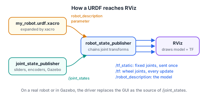
Fixed joints go to /tf_static once; moving joints are recomputed on /tf every time new joint angles arrive.
- robot_state_publisher takes the URDF as its
robot_descriptionparameter, republishes it on/robot_description, sends fixed joints on/tf_static, and turns/joint_statesinto moving transforms on/tf. - joint_state_publisher_gui stands in for encoders, publishing
/joint_statesfrom sliders. In Gazebo or on hardware, the driver publishes it instead. - RViz draws the robot from the description and TF.
Save this as launch/display.launch.py in the same package:
import os
from ament_index_python.packages import get_package_share_directory
from launch import LaunchDescription
from launch.substitutions import Command
from launch_ros.actions import Node
from launch_ros.parameter_descriptions import ParameterValue


def generate_launch_description():
    pkg = get_package_share_directory('my_robot_description')
    xacro_file = os.path.join(pkg, 'urdf', 'my_robot.urdf.xacro')
    robot_description = ParameterValue(Command(['xacro ', xacro_file]), value_type=str)

    return LaunchDescription([
        Node(package='robot_state_publisher', executable='robot_state_publisher',
             parameters=[{'robot_description': robot_description}]),
        Node(package='joint_state_publisher_gui', executable='joint_state_publisher_gui'),
        Node(package='rviz2', executable='rviz2'),
    ])
For an ament_python package, list the folders in setup.py so colcon installs them, then build and launch:
# inside setup.py, in the setup(...) call
from glob import glob
data_files=[
    ('share/ament_index/resource_index/packages', ['resource/my_robot_description']),
    ('share/my_robot_description', ['package.xml']),
    ('share/my_robot_description/urdf', glob('urdf/*.xacro')),
    ('share/my_robot_description/launch', glob('launch/*.launch.py')),
],cd ~/ros2_ws
colcon build --symlink-install --packages-select my_robot_description
source install/setup.bash
ros2 launch my_robot_description display.launch.py
ros2 run tf2_tools view_frames # writes a PDF of the TF treeIn RViz, set the fixed frame to base_footprint, add a RobotModel display with its description topic set to /robot_description, and add a TF display. Moving a wheel slider should spin that wheel.
Quick check
What does robot_state_publisher publish?
It reads the robot_description and /joint_states, then publishes fixed transforms on /tf_static and moving ones on /tf.
Common URDF and xacro mistakes
- Missing or invented inertials. Visual-only links look fine in RViz but misbehave in simulation. Use the formulas, not guesses.
- Degrees instead of radians.
rpy="0 15 0"means 15 radians, more than two full turns. Write${15*pi/180}in xacro. - Wheel axis wrong. If the wheel spins like a coin on a table, the joint origin's roll or the
axisis off. - Mesh paths. Use
package://my_robot_description/meshes/body.stlorfile://URIs, and install the meshes folder. - Forgetting the package name in
setup.py. If the urdf folder is not installed, launch finds nothing even though the file exists insrc. - Detailed meshes as collision geometry. They slow physics badly. Use boxes and cylinders for collision.
Matrix and angle mistakes are the most common source of URDF bugs; check your coordinate-geometry instincts on Debugshala Test if the transform block felt hard.
Key takeaways
- URDF describes a robot as a tree of links joined by joints, in metres and radians.
- Joint origins are transforms; chaining them gives each link's pose, exactly like forward kinematics.
- Give every simulated link visual, collision and realistic inertial blocks.
- xacro adds properties, maths and macros, and expands to plain URDF.
- robot_state_publisher plus joint states produce the TF tree that RViz, Gazebo and Nav2 rely on.
FAQ
What is the difference between URDF and xacro?
URDF is the XML format ROS tools read. xacro is a macro language that generates URDF, adding variables, arithmetic, macros and file includes. You write robot.urdf.xacro, and the xacro command or a launch file expands it into plain URDF before robot_state_publisher loads it.
What is the difference between URDF and SDF?
URDF is the ROS robot description format and can only describe a single robot as a tree. SDF is Gazebo's format and can describe whole worlds, closed loops, lights and sensors in more detail. Gazebo converts a URDF to SDF when you spawn it, using extra <gazebo> tags you add for plugins and sensors.
Can I export a URDF from CAD software?
Yes. Community exporters exist for SolidWorks, Onshape and Fusion 360, and they produce links, joints and meshes. Check the output carefully: exported frames, inertias and collision meshes often need cleaning, and many teams keep the exported meshes but write the joint structure by hand in xacro.
Why does my robot look broken or scattered in RViz?
Usually the TF tree is incomplete. If nothing publishes /joint_states, robot_state_publisher cannot place the wheel links, so RViz shows them at the origin or in red. Run a joint state publisher, check that the fixed frame exists, and use ros2 run tf2_tools view_frames to see which link is disconnected.
Where can I build and model a real robot in Indore?
A hands-on robot-building course at Debugshala runs at the Old Palasia campus. You wire sensors, motors and motor drivers, program Arduino, ESP32 and Raspberry Pi boards, and meet ROS 2 basics such as nodes and topics before a final robot project. You can attend a free demo class before deciding.
From the team behind this site
Go further with the Robotics Course at Debugshala
These tutorials are written by Debugshala, a training and placement institute at Old Palasia, Indore. The classroom course adds live mentoring, real projects and interview preparation.
- Offline classes at Old Palasia, Indore
- Free demo class before you pay
- Non-IT, fresher and year-gap friendly
- Placement assistance
700+ students placed · 200+ hiring partners · 4.9★ Google rating
