

Differential Drive Robot: Kinematics, Turning and Python Code
How a differential drive robot moves: turning radius, forward and inverse kinematics, wheel speed limits, a go-to-goal controller in Python and ROS 2 cmd_vel.
Imagine pushing a wheelchair yourself. To go straight you push both rims equally. To curve gently right you push the left rim a little harder. To spin on the spot you push one rim forward and pull the other back.
There is no steering wheel anywhere. Every move, from a straight corridor to a tight U-turn, comes from the difference between two wheel speeds.
That is exactly how most hobby robots, robot vacuums and warehouse carts move, and the maths behind it fits in four short formulas.
What is a differential drive robot?
Map the wheelchair onto a robot. The two big rims are the robot's drive wheels, each with its own motor. The small front wheels are the caster that only balances. Pushing the rims at different speeds is differential steering, and the distance between the rims is the track width, L.
A differential drive robot is a wheeled mobile robot that moves and steers using two independently powered wheels on a common axis, controlling direction purely by the difference in their speeds.
It is the most common design for beginner robots because it needs only two motors, one dual motor driver and no steering mechanism. The encoders and odometry lesson showed how to track this robot's position from wheel counts.
This lesson is about the other direction: how to make it move the way you want. It is the wheeled cousin of arm kinematics, with wheel speeds in place of joint angles.
How does a differential drive robot turn?
When the two wheels run at different speeds, the robot rotates around a point on the line through both wheels. That point is the instantaneous centre of curvature (ICC), and its distance from the robot's centre is the turning radius R.
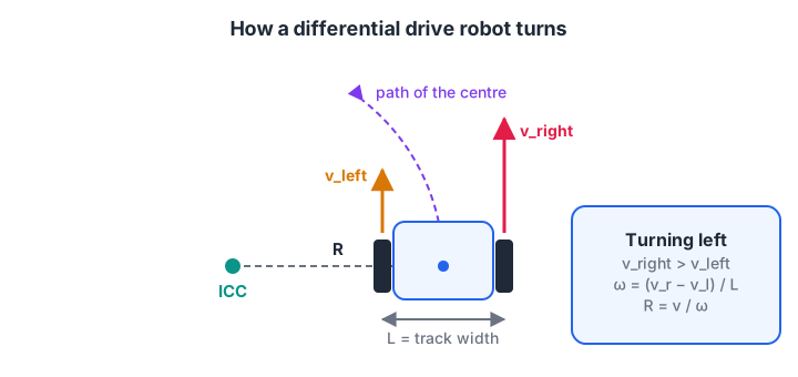
The faster wheel is on the outside of the curve; the further apart the speeds, the closer the ICC comes to the robot.
| Wheel speeds | Motion | Turning radius R |
|---|---|---|
| v_left = v_right | Straight line | Infinite |
| v_right > v_left, both forward | Gentle left curve | Larger than L/2 |
| v_left = 0, v_right forward | Pivot around the left wheel | Exactly L/2 |
| v_left = −v_right | Spin on the spot | Zero |
The turning radius formula is R = (L/2) × (v_right + v_left) / (v_right − v_left). It blows up when the speeds are equal, which is just the maths saying "straight line".
Forward kinematics: wheel speeds to robot motion
Two numbers describe how the robot body moves: linear velocity v (metres per second, forward) and angular velocity ω (radians per second, positive means turning left).
- v = (v_right + v_left) / 2
- ω = (v_right − v_left) / L
Each wheel's ground speed comes from its motor: v_wheel = wheel radius × wheel angular speed. This block evaluates the formulas for the cases in the table, for a robot with 15 cm track width.
L = 0.15                         # track width, metres

def body_motion(v_left, v_right):
    v = (v_right + v_left) / 2
    w = (v_right - v_left) / L
    R = float("inf") if w == 0 else v / w        # same as (L/2)(vr+vl)/(vr-vl)
    return v, w, R

cases = [(0.20, 0.20), (0.15, 0.25), (0.00, 0.20), (-0.10, 0.10), (0.25, 0.15)]
print(" v_left  v_right |   v m/s  omega rad/s  radius m")
for vl, vr in cases:
    v, w, R = body_motion(vl, vr)
    print(f"{vl:7.2f} {vr:8.2f} | {v:7.2f} {w:11.2f} {R:9.3f}")
The pivot case gives R = 0.075 m, exactly half the track width, so the centre circles the stopped wheel. The last row swaps the speeds and the turn rate becomes negative, a right turn.
Quick check
A robot with track width 0.2 m has v_left = 0.1 m/s and v_right = 0.3 m/s. What is its angular velocity?
ω = (0.3 − 0.1) / 0.2 = 1.0 rad/s. The right wheel is faster, so the robot turns left.
Inverse kinematics: from desired motion to wheel speeds
Your navigation code usually decides "go forward at 0.2 m/s while turning at 1 rad/s". Inverting the two formulas gives the wheel speeds needed:
- v_right = v + ω × L / 2 and v_left = v − ω × L / 2.
- Convert each to wheel RPM: rpm = v_wheel / (2π × wheel radius) × 60.
- If either wheel would exceed the motor's maximum, scale both down by the same factor. That keeps the curve's shape and only slows the robot.
- Map RPM to a PWM duty for the motor driver, or better, hand it to a PID speed loop per wheel.
Step 3 matters more than it looks. If you simply clip the faster wheel, the robot turns less than intended and drifts off its path.
import math

L, r, MAX_RPM = 0.15, 0.033, 200          # track, wheel radius (m), motor limit

def wheel_rpm(v, w):
    vr, vl = v + w * L / 2, v - w * L / 2
    to_rpm = lambda s: s / (2 * math.pi * r) * 60
    rr, rl = to_rpm(vr), to_rpm(vl)
    peak = max(abs(rr), abs(rl))
    scale = min(1.0, MAX_RPM / peak) if peak else 1.0
    return rl * scale, rr * scale, scale

for v, w in [(0.2, 0.0), (0.2, 1.0), (0.0, 3.0), (0.6, 2.0)]:
    rl, rr, k = wheel_rpm(v, w)
    v_out = (rr + rl) / 2 / 60 * 2 * math.pi * r
    w_out = (rr - rl) / 60 * 2 * math.pi * r / L
    radius = f"{v_out / w_out:.3f} m" if w_out else "straight"
    print(f"want v={v:.1f} w={w:.1f} -> left {rl:6.1f} rpm, right {rr:6.1f} rpm, "
          f"scale {k:.2f}, radius {radius}")
The last command asks for more than the motors can give, so both wheels are scaled to 0.92 of the request. The turning radius stays at 0.3 m, just as commanded, only slower.
Why a differential drive robot cannot move sideways
A wheel rolls forward and backward but resists sliding sideways. So at any moment the robot can only move along the direction it faces, or rotate. This rule is called a nonholonomic constraint.
The robot can still reach any position and heading, just not directly. Think of parallel parking: you get there by combining forward motion and turning. Here is how it compares with other wheeled bases:
| Drive type | Motors | Can move sideways? | Notes |
|---|---|---|---|
| Differential drive | 2 | No | Simple, cheap, spins on the spot |
| Skid steer (4 wheels) | 2 or 4 | No | Rough terrain, but wheels scrub on turns, so odometry is poor |
| Car-like (Ackermann) | 1 drive + 1 steering | No | Cannot spin on the spot, needs room to turn |
| Mecanum or omni wheels | 4 (or 3) | Yes | Holonomic, but more expensive and slips more |
Quick check
What does a nonholonomic constraint mean for a differential drive robot?
The wheels resist sliding sideways, so the robot must combine driving and turning to reach a position beside it.
Go-to-goal control: driving to a point
Combine the constraint with a simple controller: turn towards the goal, and drive forward faster when you are facing it. This is a pair of proportional controllers.
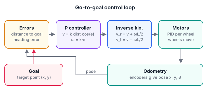
The controller thinks in v and ω; inverse kinematics translates that into what each motor must do.
import math

L, dt = 0.15, 0.05
x, y, th = 0.0, 0.0, 0.0                  # start at origin facing +x
goal = (1.0, 0.6)
K_LIN, K_ANG, V_MAX = 0.8, 3.0, 0.3

for step in range(400):
    dx, dy = goal[0] - x, goal[1] - y
    dist = math.hypot(dx, dy)
    if dist < 0.02:
        break
    err = math.atan2(dy, dx) - th
    err = math.atan2(math.sin(err), math.cos(err))      # wrap to [-pi, pi]
    v = min(V_MAX, K_LIN * dist) * max(0.0, math.cos(err))   # slow when facing away
    w = K_ANG * err
    vl, vr = v - w * L / 2, v + w * L / 2               # inverse kinematics
    v, w = (vr + vl) / 2, (vr - vl) / L                 # what the wheels produce
    x += v * math.cos(th) * dt; y += v * math.sin(th) * dt; th += w * dt
    if step % 20 == 0:
        print(f"t={step * dt:4.1f}s  x={x:.2f} y={y:.2f} heading={math.degrees(th):5.1f}  "
              f"wheels L={vl:+.2f} R={vr:+.2f} m/s  dist={dist:.2f}")
print(f"reached goal in {step * dt:.1f} s at ({x:.3f}, {y:.3f})")
At the start the goal is 31 degrees to the left, so the right wheel runs faster. As the heading error shrinks, the wheel speeds converge and the robot straightens out, then slows as the distance falls. The cos(err) factor stops the robot charging forward when the goal is behind it.
This controller only knows a single point. Following a full route around obstacles needs a path first, which is the job of path planning with A* and Dijkstra.
Driving a differential drive robot in ROS 2
In ROS 2 the standard command for a mobile base is a velocity message: linear.x is v and angular.z is ω. A base driver, a simulator or ros2_control's diff_drive_controller then performs the inverse kinematics for you. This node, written for ROS 2 Jazzy, drives the robot in a 0.4 m radius circle.
import rclpy
from rclpy.node import Node
from geometry_msgs.msg import Twist

class CircleDriver(Node):
    def __init__(self):
        super().__init__('circle_driver')
        self.pub = self.create_publisher(Twist, '/cmd_vel', 10)
        self.timer = self.create_timer(0.1, self.tick)   # 10 Hz

    def tick(self):
        msg = Twist()
        msg.linear.x = 0.2      # v, m/s
        msg.angular.z = 0.5     # omega, rad/s -> radius 0.4 m
        self.pub.publish(msg)

def main():
    rclpy.init()
    node = CircleDriver()
    rclpy.spin(node)
    node.destroy_node()
    rclpy.shutdown()

if __name__ == '__main__':
    main()
Gazebo's diff drive plugin and many robot drivers listen for plain Twist on /cmd_vel. Recent diff_drive_controller releases expect the time-stamped TwistStamped version instead, so check the documentation for the controller you use. The ROS 2 basics lesson explains publishers and topics if they are new to you.
Common differential drive mistakes
- Measuring L wrong. Use the distance between the wheels' contact points, not the chassis width.
- Clipping one wheel instead of scaling both. It silently changes the turn you asked for.
- Not wrapping angle errors. Without wrapping to ±π, a robot at 179 degrees aiming for −179 degrees spins almost a full circle.
- Ignoring motor dead band. Small PWM values may not move the wheels at all, so low-speed turns stall.
- A caster that drags. A stiff or badly placed caster pulls the robot sideways and fights the kinematics.
Key takeaways
- A differential drive robot steers only with the speed difference between two wheels.
- Forward kinematics: v = (v_right + v_left) / 2 and ω = (v_right − v_left) / L.
- Inverse kinematics: v_right = v + ωL/2 and v_left = v − ωL/2; scale both wheels together when limits are hit.
- The robot cannot slide sideways, so controllers turn towards the goal while driving.
- In ROS 2, you command it with v and ω on
/cmd_vel, and the controller does the wheel maths.
FAQ
What is the difference between differential drive and skid steering?
Differential drive uses two driven wheels and a caster, so the wheels roll cleanly during turns. Skid steering uses four or more driven wheels, usually linked in pairs per side, and turns by making the wheels slide. Skid steer handles rough ground better but wastes energy and gives much less reliable odometry.
Why does my two-wheel robot not drive straight?
Two motors of the same model rarely run at exactly the same speed for the same PWM value. Use wheel encoders and a PID speed loop for each wheel, or at minimum trim one side's PWM. Also check that the wheels are the same size and the caster swivels freely.
How do I calculate the turning radius of a differential drive robot?
The turning radius is R = (L/2) × (v_right + v_left) / (v_right − v_left), measured from the robot's centre. You can also compute R = v / ω. Equal wheel speeds give an infinite radius, a straight line, and equal but opposite speeds give zero, a spin on the spot.
Is a differential drive robot good for a beginner project?
Yes. It needs only two DC gear motors, a dual motor driver such as the TB6612FNG or L298N, a caster and a microcontroller. Line-following and obstacle-avoiding robots are both usually differential drive, which makes it the natural first mobile robot.
Can I build a two-wheel robot in a classroom in Indore?
Yes. You can join the Indore robotics course where you build a line follower and an obstacle-avoiding robot at Debugshala's Old Palasia campus, working with DC motors, motor drivers, Arduino, ESP32 and ROS 2 basics, in English and Hindi. A free demo class comes first, and you can try coding challenges on Debugshala Test at home.
From the team behind this site
Go further with the Robotics Course at Debugshala
These tutorials are written by Debugshala, a training and placement institute at Old Palasia, Indore. The classroom course adds live mentoring, real projects and interview preparation.
- Offline classes at Old Palasia, Indore
- Free demo class before you pay
- Non-IT, fresher and year-gap friendly
- Placement assistance
700+ students placed · 200+ hiring partners · 4.9★ Google rating
