

Wheel Encoders and Odometry: Track a Robot's Position in Code
Learn how wheel encoders and quadrature decoding work, read them with Arduino interrupts, and compute differential drive odometry in Python, including drift.
Imagine the power goes off in your hostel at night and you need to get from your room to the water cooler at the end of the corridor.
You cannot see, but you know the cooler is 24 steps straight ahead, then 6 steps after a right turn. You count each step and each turn, and you arrive close to the cooler.
Close, but not exactly. Some steps were shorter, and your right turn was not a perfect 90 degrees. On a longer route the small errors add up until you bump into a wall.
That is odometry: estimating where you are by counting your own movements, with errors that grow the further you go.
What are wheel encoders and odometry?
Map the dark corridor onto a robot. Each step is an encoder count, one small slice of wheel rotation. Knowing your step length is knowing your wheel's circumference and the counts per revolution. Counting turns is comparing how far the left and right wheels have travelled. And bumping into the wall after a long walk is odometry drift.
A wheel encoder is a rotation sensor that outputs pulses as a wheel or motor shaft turns, and odometry is the method of estimating a robot's position and heading by adding up the wheel motions measured by those encoders.
Odometry is the first localisation method almost every mobile robot uses: fast, cheap and available anywhere. It is also the starting point for the IMU fusion, Kalman filtering and SLAM covered later in this series.
Types of wheel encoders
| Type | How it senses | Pros | Cons | Common in |
|---|---|---|---|---|
| Optical slotted disc | An IR beam shines through slots in a disc | Cheap, easy to understand | Dust and sunlight cause false counts, often single channel | Hobby kits with 20-slot discs |
| Magnetic (Hall effect) | A magnet ring passes Hall sensors | Sealed, robust, two channels | Lower counts per motor turn | Gear motors such as N20 and 25 mm motors with built-in encoders |
| Optical quadrature | Fine patterned disc read by two sensors | High resolution | More expensive, more fragile | Industrial motors, precise arms |
| Absolute | Reports the actual angle, not just pulses | Knows position at power-up | Costly, complex interface | Robot arm joints |
Mobile robots mostly use incremental encoders, which report changes, not an absolute angle. Odometry only needs the change since the last update.
How a quadrature encoder detects direction
A single-channel encoder counts pulses but cannot tell forward from backward. A quadrature encoder has two channels, A and B, offset by a quarter of a cycle. Whichever channel changes first tells you the direction.
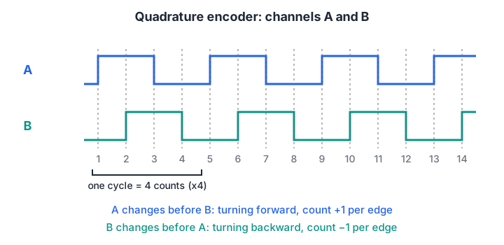
Every rising and falling edge on either channel is a countable event, so one pulse cycle gives up to four counts.
The two channels together form a two-bit state that steps through a fixed cycle: 00, 10, 11, 01 going forward, and the reverse going backward. A decoder reads the old and new states, looks up whether the change means +1 or −1, and ignores impossible jumps. This lookup approach is common in firmware because it is fast and noise-tolerant.
# Index = old_state * 4 + new_state, where state = (A << 1) | B
TABLE = [0, -1, 1, 0,   1, 0, 0, -1,   -1, 0, 0, 1,   0, 1, -1, 0]

def decode(samples):
    count, old = 0, samples[0]
    for a, b in samples[1:]:
        new = (a << 1) | b
        count += TABLE[((old[0] << 1) | old[1]) * 4 + new]
        old = (a, b)
    return count

forward = [(0, 0), (1, 0), (1, 1), (0, 1)] * 5 + [(0, 0)]   # A leads B
backward = forward[::-1]
wobble = [(0, 0), (1, 0), (0, 0), (1, 0), (1, 1), (1, 0), (1, 1), (0, 1)]

print("forward, 5 cycles :", decode(forward), "counts")
print("backward, 5 cycles:", decode(backward), "counts")
print("wobbling in place :", decode(wobble), "counts (net movement only)")
Five forward cycles give +20 counts, which is four counts per cycle, called x4 decoding. The wobble test shows why quadrature matters: a wheel rocking back and forth over an edge would fool a single-channel counter into counting up, while the decoder correctly reports only the net movement.
Counts per revolution and distance per count
The number that ties encoder counts to the real world is counts per wheel revolution. For a motor-shaft encoder with a gearbox:
counts per wheel rev = pulses per motor rev × gear ratio × 4 (for x4 decoding)
Take a gear motor with an 11-pulse Hall encoder on the motor shaft and a 1:30 gearbox, driving a 65 mm wheel. That gives 11 × 30 × 4 = 1,320 counts per wheel revolution.
The wheel's circumference is π × 65 = 204.2 mm, so each count is about 0.155 mm of travel. Check your motor's datasheet for its actual pulse count and gear ratio.
Quick check
Why does a quadrature encoder need two channels?
A and B are a quarter cycle apart. Which one changes first tells the decoder whether the wheel is turning forward or backward.
Reading encoders on an Arduino with interrupts
Encoder pulses arrive thousands of times a second, too fast to catch by checking pins in loop(). Instead you attach an interrupt: on every edge the chip pauses and runs a tiny function. On an Uno, pins 2 and 3 are the external interrupt pins.
// One quadrature encoder on an Arduino Uno, x4 decoding
const byte ENC_A = 2, ENC_B = 3;
const int8_t TABLE[16] = {0,-1,1,0, 1,0,0,-1, -1,0,0,1, 0,1,-1,0};

volatile long ticks = 0;
volatile byte lastState = 0;

void onEdge() {
  byte s = (digitalRead(ENC_A) << 1) | digitalRead(ENC_B);
  ticks += TABLE[(lastState << 2) | s];
  lastState = s;
}

void setup() {
  pinMode(ENC_A, INPUT_PULLUP);
  pinMode(ENC_B, INPUT_PULLUP);
  lastState = (digitalRead(ENC_A) << 1) | digitalRead(ENC_B);
  attachInterrupt(digitalPinToInterrupt(ENC_A), onEdge, CHANGE);
  attachInterrupt(digitalPinToInterrupt(ENC_B), onEdge, CHANGE);
  Serial.begin(115200);
}

void loop() {
  static long lastTicks = 0;
  noInterrupts();               // copy the 4-byte counter safely
  long now = ticks;
  interrupts();
  long delta = now - lastTicks;
  lastTicks = now;
  float mmPerTick = PI * 65.0 / 1320.0;
  Serial.print("ticks="); Serial.print(now);
  Serial.print("  speed="); Serial.print(delta * mmPerTick * 10.0); Serial.println(" mm/s");
  delay(100);                   // 10 updates per second
}
The counter is volatile because it changes inside an interrupt, and loop() copies it with interrupts paused because an 8-bit chip reads a long in several steps.
Two wheels need two encoders, so on an Uno give each encoder one interrupt pin (x2 decoding) or use an ESP32, where any pin can interrupt. The speed you measure here is exactly the feedback a PID speed controller needs.
How wheel odometry works on a differential drive robot
With an encoder on each wheel, you know the distance each wheel rolled since the last update, d_left and d_right. Two simple formulas turn them into motion.
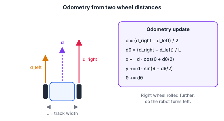
If both wheels roll the same distance, the robot goes straight. If the right wheel rolls further, it turns left.
- Forward distance of the robot's centre:
d = (d_right + d_left) / 2. - Change in heading, in radians:
dθ = (d_right − d_left) / L, where L is the distance between the wheels (the track width). - Update position, using the average heading during the step:
x += d × cos(θ + dθ/2)andy += d × sin(θ + dθ/2). - Update heading:
θ += dθ. - Repeat every update, typically 20 to 100 times a second.
The full motion model of this robot type, including how to turn a desired speed into wheel speeds, is covered in differential drive robots.
Odometry in Python, and why it drifts
This block runs odometry on encoder counts for a robot told to drive a 1 metre square. The twist: the real left wheel is 1 percent larger than the code believes, as happens with a slightly softer tyre.
import math

R_NOMINAL, TRACK, CPR = 32.5, 150.0, 1320          # mm, mm, counts per wheel rev
MM_PER_COUNT = 2 * math.pi * R_NOMINAL / CPR

def odom(pose, cl, cr):
    x, y, th = pose
    dl, dr = cl * MM_PER_COUNT, cr * MM_PER_COUNT
    d, dth = (dl + dr) / 2, (dr - dl) / TRACK
    return (x + d * math.cos(th + dth / 2), y + d * math.sin(th + dth / 2), th + dth)

# Counts the planner sends for a 1000 mm side, then a 90 degree left turn on the spot
side = round(1000 / MM_PER_COUNT)
turn = round((math.pi / 2) * TRACK / 2 / MM_PER_COUNT)
plan = [(side, side), (-turn, turn)] * 4

believed, actual = (0.0, 0.0, 0.0), (0.0, 0.0, 0.0)
for cl, cr in plan:
    for _ in range(50):                             # 50 small updates per segment
        believed = odom(believed, cl / 50, cr / 50)
        actual = odom(actual, cl / 50 * 1.01, cr / 50)   # left wheel really 1% bigger
print(f"odometry thinks: x={believed[0]:7.1f} mm  y={believed[1]:7.1f} mm")
print(f"robot is really: x={actual[0]:7.1f} mm  y={actual[1]:7.1f} mm")
print(f"position error after 4 m: {math.dist(believed[:2], actual[:2]):.0f} mm, "
      f"heading error {math.degrees(actual[2] - believed[2]):.1f} degrees")
The odometry reports a perfect square ending within 2 mm of the start, because it only sees the counts it expected. The real robot ends up about 17 cm away and pointing 13 degrees off. A tiny 1 percent calibration error grows with every metre and especially every turn, because heading errors bend all later motion.
Quick check
The left wheel rolls 100 mm and the right wheel rolls 130 mm. The track width is 150 mm. What is the change in heading?
dθ = (130 − 100) / 150 = 0.2 radians, about 11.5 degrees. A larger right-wheel distance turns the robot left.
Why odometry drifts and how to reduce it
Systematic errors repeat the same way every time and can be calibrated out:
- unequal wheel diameters, from tyres or manufacturing
- a wrong track width in the code
- encoder resolution or gear ratio set incorrectly
Random errors cannot be calibrated, only limited:
- wheel slip on smooth tiles, dust or carpet edges
- bumps and uneven floors
- sudden acceleration that spins the wheels
A simple calibration routine
- Drive straight for 2 metres and measure the real distance with a tape. Scale the mm-per-count value by real ÷ reported.
- Drive straight again and see whether the robot curves. Adjust the left and right wheel radii slightly until it stops curving.
- Spin the robot on the spot ten full turns and compare the odometry heading with reality. Adjust the track width in the code until they match.
Even after calibration, slip means odometry is only trusted over short distances. Real robots combine it with a gyroscope, as in IMU and sensor fusion, and correct the combined estimate with a Kalman filter or with landmarks. In ROS 2, wheel odometry is usually published as a nav_msgs/msg/Odometry message on the /odom topic for other nodes to use.
Common mistakes with wheel encoders
- Polling instead of interrupts. Checking pins in
loop()misses pulses as soon as the wheel speeds up. - Reading a multi-byte counter while it changes. Copy it with interrupts paused.
- Forgetting the gearbox. Counts per wheel revolution must include the gear ratio and the decoding mode.
- Wrong sign on one side. The two wheels face opposite directions, so one encoder counts backwards when the robot drives forward. Flip it in code.
- Trusting odometry forever. Errors grow without limit. Reset or correct the estimate from other sensors.
Key takeaways
- Encoders turn wheel rotation into countable pulses; quadrature adds direction.
- Counts per wheel rev = encoder pulses × gear ratio × decoding factor.
- Read encoders with interrupts, and copy shared counters safely.
- Odometry: average the wheel distances for travel, divide their difference by the track width for heading.
- Odometry drifts; calibrate wheel size and track width, then fuse it with other sensors.
FAQ
What is odometry in robotics?
Odometry in robotics is estimating a robot's position and heading by integrating its own motion, usually from wheel encoder counts. It needs no external reference, so it works anywhere, but its error grows with distance travelled because slip and calibration errors accumulate.
How accurate is wheel odometry?
A well-calibrated small robot on a clean, hard floor can stay within a few centimetres over a few metres. Accuracy falls on carpet, dusty floors and with frequent turns. Treat odometry as reliable for short-term motion and correct it with an IMU, cameras or landmarks.
What is the difference between PPR and CPR in encoders?
PPR, pulses per revolution, is the number of full pulse cycles on one channel per revolution. CPR, counts per revolution, is the number of edges you count after decoding, which is up to four times the PPR with x4 quadrature decoding. Datasheets use these terms inconsistently, so check by turning the wheel once.
Where can I learn robot sensors and motor feedback in Indore?
Debugshala's practical robotics course for Indore learners covers sensors, DC motors and motor drivers on Arduino and ESP32, line-follower and obstacle-avoiding robots, and ROS 2 basics. It runs at the Old Palasia campus in English and Hindi with a free demo class, and you can practise with coding quizzes on Debugshala Test.
From the team behind this site
Go further with the Robotics Course at Debugshala
These tutorials are written by Debugshala, a training and placement institute at Old Palasia, Indore. The classroom course adds live mentoring, real projects and interview preparation.
- Offline classes at Old Palasia, Indore
- Free demo class before you pay
- Non-IT, fresher and year-gap friendly
- Placement assistance
700+ students placed · 200+ hiring partners · 4.9★ Google rating
