

Robot Sensors and Actuators: Motors, PWM and Filtering Explained
Robot sensors and actuators explained: ultrasonic, IR, IMU, encoders, DC motors, servos, H-bridge drivers, PWM and noise filters, with Python demos.
Imagine driving a scooter through Indore at night with a cracked helmet visor. Your view of the road ahead wobbles, a streetlight flickers in your eyes, and the speedometer needle jitters. You still ride safely, because your brain combines what you see, what you feel through the handlebars and what you heard a second ago into one steady picture.
Your hands and feet then do the work: a little more throttle here, a gentle brake there, a lean into the curve.
A robot faces the same two problems. It has to measure a messy world and move in it with control. Sensors are its eyes and inner ear. Actuators are its hands and feet. And software, like your brain, has to clean up the noise in between.
What are robot sensors and actuators?
In the scooter story, your eyes are a camera, your sense of balance is an IMU, the speedometer is a wheel encoder, and the throttle and brakes are actuators controlled through a motor driver. The jitter you mentally ignore is sensor noise, and the smoothing your brain does is filtering.
A sensor converts a physical quantity such as distance, light, rotation or acceleration into an electrical signal the controller can read, and an actuator converts an electrical command from the controller into physical motion or action.
Common robot sensors and how they work
Ultrasonic distance sensor
The HC-SR04 style sensor sends a short burst of 40 kHz sound and times the echo. Sound travels about 343 metres per second at room temperature, so distance in centimetres is echo time in µs × 0.0343 / 2.
You divide by two because the sound goes out and back. Typical hobby modules work from a few centimetres to a few metres. Soft surfaces like curtains and walls hit at a sharp angle can swallow the echo and produce wild readings.
IR line sensor
An infrared LED shines at the floor and a phototransistor measures what bounces back. White surfaces reflect a lot, black tape absorbs most of it. A line follower uses two to eight of these in a row and steers to keep the line centred. Sunlight contains infrared too, so these sensors can misbehave near a bright window.
IMU (inertial measurement unit)
An IMU such as the common 6-axis MPU-6050 combines an accelerometer (measures acceleration, including gravity, so it knows which way is down) and a gyroscope (measures how fast the robot is rotating). Some add a magnetometer as a compass. The accelerometer is noisy but does not drift; the gyroscope is smooth but slowly drifts. You will combine the two later.
Wheel encoders
An encoder counts pulses as a wheel turns. If an encoder gives 20 pulses per revolution and the wheel is 6.5 cm across, each pulse is about 1 cm of travel (π × 6.5 / 20). A quadrature encoder has two channels offset from each other, so the order of the pulses also tells you the direction.
Camera
A camera gives the richest data: lines, colours, objects, faces, QR codes. It also needs the most computing, which is why vision robots usually carry a Raspberry Pi or a similar board running OpenCV, rather than only a microcontroller. Arduino vs ESP32 vs Raspberry Pi explains that trade-off.
Actuators: DC motors, servos and steppers
| Actuator | What you control | Typical use | Needs |
|---|---|---|---|
| DC gear motor | Speed (PWM) and direction | Robot wheels, fans, pumps | A motor driver (H-bridge) |
| Servo motor | Angle, usually 0 to 180 degrees | Steering, grippers, sensor pan | A 50 Hz control pulse, its own power |
| Stepper motor | Exact number of steps (often 200 per turn) | 3D printers, camera sliders, precise positioning | A stepper driver |
A servo has a small motor, gears and a position sensor inside. You send a pulse every 20 ms; a pulse of about 1 ms means one end of travel, 1.5 ms means centre, and about 2 ms means the other end (exact limits vary by model).
A stepper moves in fixed increments, so it can position precisely without feedback, but it can silently skip steps if overloaded.
Motor drivers and the H-bridge
A microcontroller pin cannot power a motor, and it can only output a positive voltage, so on its own it cannot reverse one. A motor driver solves both. Its core is the H-bridge: four switches around the motor, named for the shape they make.
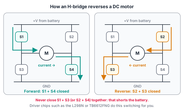
Close one diagonal pair and current flows left to right; close the other pair and it flows right to left, so the motor reverses.
In a real driver the "switches" are transistors controlled by logic pins. On an L298N board, the IN1 and IN2 pins choose the direction for motor A and the ENA pin takes a PWM signal for speed.
The L298N is cheap and everywhere, but it wastes a couple of volts as heat; MOSFET-based drivers such as the TB6612FNG are more efficient for small robots.
PWM explained: controlling speed with fast switching
A light dimmer in a fan regulator varies resistance. A microcontroller does something cleverer: it switches the motor fully on and fully off hundreds or thousands of times a second. This is pulse-width modulation (PWM). The fraction of each cycle spent on is the duty cycle.
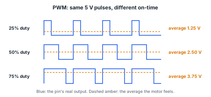
The motor is too slow to follow each pulse, so it responds to the average voltage.
On a classic Arduino, analogWrite(pin, value) takes a value from 0 to 255, so duty = value / 255. The average voltage is duty × supply voltage. The Python below computes this for a few values and also works out servo pulse widths, using the operators you already know.
SUPPLY = 7.4        # battery voltage reaching the motor driver
FREQ = 490          # default PWM frequency on most classic Uno pins, in Hz

period_ms = 1000 / FREQ
print(f"PWM period: {period_ms:.3f} ms\n")
print("value  duty   on-time(ms)  avg volts")
for value in [0, 64, 128, 191, 255]:
    duty = value / 255
    on_ms = duty * period_ms
    print(f"{value:5}  {duty:5.0%}  {on_ms:10.3f}  {duty * SUPPLY:8.2f}")

print("\nServo pulse for a 1.0 to 2.0 ms servo (20 ms frame):")
for angle in [0, 45, 90, 135, 180]:
    pulse = 1.0 + angle / 180
    print(f"  {angle:3} deg -> {pulse:.2f} ms pulse, duty {pulse / 20:.1%}")
Notice that a servo's duty cycle is small (5% to 10%). Servos read the pulse width, not the average voltage, which is why they need the special Servo library rather than plain analogWrite.
Quick check
An Arduino calls analogWrite(pin, 128) on a 5 V pin. Roughly what average voltage does the motor see?
128 / 255 is about 50% duty, and 50% of 5 V is about 2.5 V on average.
Sensor noise and filtering
Every sensor reading is the true value plus some noise. An ultrasonic sensor might read 52, 49, 51, 140, 50 cm when the wall is really 50 cm away. That 140 is a spike from a stray echo, and if your robot reacts to it, it will do something strange.
Moving average and median filters
A moving average replaces each reading with the mean of the last few. It smooths jitter but lets a big spike leak through, partly. A median filter takes the middle value of the last few, which throws spikes away completely.
import random
random.seed(3)

true_cm = 50
raw = [true_cm + random.gauss(0, 2) for _ in range(15)]
raw[6] = 140                          # one bad echo

def moving_avg(xs, n=5):
    return [sum(xs[max(0, i - n + 1):i + 1]) / len(xs[max(0, i - n + 1):i + 1]) for i in range(len(xs))]

def median_filter(xs, n=5):
    out = []
    for i in range(len(xs)):
        window = sorted(xs[max(0, i - n + 1):i + 1])
        out.append(window[len(window) // 2])
    return out

avg, med = moving_avg(raw), median_filter(raw)
print(" i    raw   moving-avg   median")
for i in range(len(raw)):
    print(f"{i:2} {raw[i]:6.1f} {avg[i]:10.1f} {med[i]:8.1f}")
Look at rows 6 to 10. The moving average jumps up to the high 60s for several readings, while the median barely notices the spike.
Complementary filter for an IMU
To estimate tilt, you have two imperfect sources. Integrating the gyroscope is smooth but drifts away over time. The accelerometer angle is correct on average but jumps around.
A complementary filter trusts the gyro in the short term and gently pulls towards the accelerometer in the long term: angle = 0.98 × (angle + gyro × dt) + 0.02 × accel_angle.
import numpy as np
rng = np.random.default_rng(1)

dt, steps = 0.01, 500                    # 100 Hz for 5 seconds
true = 10 * np.sin(np.linspace(0, 3, steps))           # real tilt, degrees
true_rate = np.gradient(true, dt)
gyro = true_rate + 1.5 + rng.normal(0, 0.5, steps)     # 1.5 deg/s bias + noise
accel = true + rng.normal(0, 3.0, steps)               # noisy but unbiased

g_only, comp = 0.0, 0.0
g_hist, c_hist = [], []
for i in range(steps):
    g_only += gyro[i] * dt
    comp = 0.98 * (comp + gyro[i] * dt) + 0.02 * accel[i]
    g_hist.append(g_only); c_hist.append(comp)

for name, est in [("gyro only", g_hist), ("accel only", accel), ("complementary", c_hist)]:
    err = np.abs(np.array(est) - true)
    print(f"{name:14} mean error {err.mean():5.2f} deg   final error {err[-1]:5.2f} deg")
The gyro-only estimate wanders steadily away, the accelerometer is jumpy, and the complementary filter beats both with two lines of maths. More advanced robots use a Kalman filter, which picks the weights automatically.
Quick check
Which filter best removes a single large spike from distance readings?
The median ignores a lone outlier, while an average spreads it across several outputs.
Common mistakes with sensors and actuators
- Powering servos or motors from the board's 5 V pin. Stalled motors pull large currents and reset the controller.
- No common ground. The driver cannot understand the controller's signals without a shared reference.
- Pinging ultrasonic sensors too fast. Leave a few tens of milliseconds between pings, or old echoes confuse new readings.
- Ignoring motor noise. Motors inject electrical noise; add capacitors across motor terminals and keep sensor wires away from motor wires.
- Over-filtering. A 50-sample average is smooth but so slow that the robot reacts late. Filter just enough.
Key takeaways
- Ultrasonic, IR, IMU, encoders and cameras cover most beginner robot sensing.
- DC motors, servos and steppers each control a different thing: speed, angle or exact steps.
- An H-bridge reverses a motor by switching diagonal pairs; a motor driver packages this for you.
- PWM duty cycle sets the average voltage a motor feels.
- Filter noisy data: median for spikes, moving average for jitter, complementary filter for IMUs.
FAQ
Which sensor should I use for an obstacle-avoiding robot?
An ultrasonic sensor is the usual first choice because it is cheap and measures real distance. IR proximity sensors are smaller but more affected by surface colour and sunlight. Our obstacle-avoiding robot project uses an HC-SR04 with an L298N driver.
Why does my servo jitter?
Common causes are a weak power supply, a shared supply with motors, or a noisy signal wire. Give servos their own regulated 5 V supply, share ground with the controller, and avoid running the signal wire alongside motor wires.
What is the difference between an L298N and a TB6612FNG?
Both are dual H-bridge motor drivers. The L298N uses older transistors that drop a couple of volts and run hot, while the TB6612FNG uses MOSFETs, wastes less power and is smaller, but handles less current. For small battery robots, the more efficient driver usually gives better speed and run time.
Can I learn robot electronics and safe wiring in Indore?
Yes. Hands-on robotics classes at Old Palasia at Debugshala cover electronics basics and safe wiring, distance, line, temperature and motion sensors, and DC motors, servos and motor drivers, all inside real builds. You can join a free demo class first.
From the team behind this site
Go further with the Robotics Course at Debugshala
These tutorials are written by Debugshala, a training and placement institute at Old Palasia, Indore. The classroom course adds live mentoring, real projects and interview preparation.
- Offline classes at Old Palasia, Indore
- Free demo class before you pay
- Non-IT, fresher and year-gap friendly
- Placement assistance
700+ students placed · 200+ hiring partners · 4.9★ Google rating
