

Obstacle Avoiding Robot Project with Arduino and HC-SR04
Build an obstacle avoiding robot with Arduino, HC-SR04 and L298N: parts list, wiring, a state-machine sketch, a Python simulation and debugging tips.
Think about the auto-rickshaw driver who takes you through the lanes behind Rajwada. He does not plan the whole route at once.
He drives at a steady pace while the lane is clear, slows when a cow or a handcart appears ahead, stops if it is too close, reverses a little if he must, turns into the next gap, and carries on.
He works in modes: cruising, slowing, reversing, turning. Each mode has a clear rule for when to switch to the next. Nobody taught him a state machine, but that is exactly what he is running.
Your first autonomous robot works the same way. It does not need a map or a camera, just one distance sensor and a few well-chosen rules.
What is an obstacle-avoiding robot?
Map the auto driver onto the robot. His eyes on the lane become the ultrasonic sensor. His modes become states in your code. His rules for switching, "too close, so stop and reverse", become transitions. His hands and feet on the handlebar and throttle become the motor driver and two DC motors.
An obstacle-avoiding robot is a mobile robot that measures the distance to objects ahead and automatically changes its motion, slowing, reversing or turning, so that it keeps moving without hitting anything.
It is the classic first robotics project because it uses every part of the sense–think–act loop described in what is robotics, with almost no mechanical difficulty.
Parts list and wiring
Parts list
| Part | Quantity | Notes |
|---|---|---|
| 2WD robot chassis with two geared DC motors ("TT" motors), wheels and a caster | 1 | Any small acrylic or metal kit works |
| Arduino Uno (or a compatible board) | 1 | Plus a USB cable for programming |
| L298N dual motor driver module | 1 | A TB6612FNG module also works with small code changes |
| HC-SR04 ultrasonic sensor | 1 | 5 V module, suits the Uno directly |
| 2 × 18650 Li-ion cells with holder and switch | 1 set | Roughly 7.4 V; use protected cells and a proper charger |
| Jumper wires (male–female and male–male) | 20 or so | |
| Small screws, standoffs, double-sided tape | A few | To mount the sensor firmly at the front |
Wiring the robot
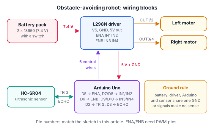
Power flows from the battery into the driver; control signals flow from the Arduino; every ground is shared.
- Battery to driver. Battery positive goes through the switch to the L298N's motor supply terminal (often labelled 12V or VS), and battery negative to its GND terminal.
- Driver to motors. Left motor to OUT1 and OUT2, right motor to OUT3 and OUT4. If a wheel spins backwards later, swap that motor's two wires.
- Driver to Arduino power. With the L298N's 5 V regulator jumper in place, its 5V terminal can power the Uno's 5V pin. Connect the L298N GND to an Arduino GND as well. Don't also power the Uno from USB and this 5 V line at the same time while driving.
- Control pins. Remove the jumpers on ENA and ENB so you can control speed. ENA → D5, IN1 → D7, IN2 → D8, ENB → D6, IN3 → D9, IN4 → D10. D5 and D6 are PWM pins, which the speed control needs.
- Sensor. HC-SR04 VCC → 5V, GND → GND, TRIG → D2, ECHO → D3.
The state machine behind the robot
Writing the logic as a state machine keeps it clear and easy to debug. At any moment, the robot is in exactly one state, and each loop it checks whether a transition should fire.
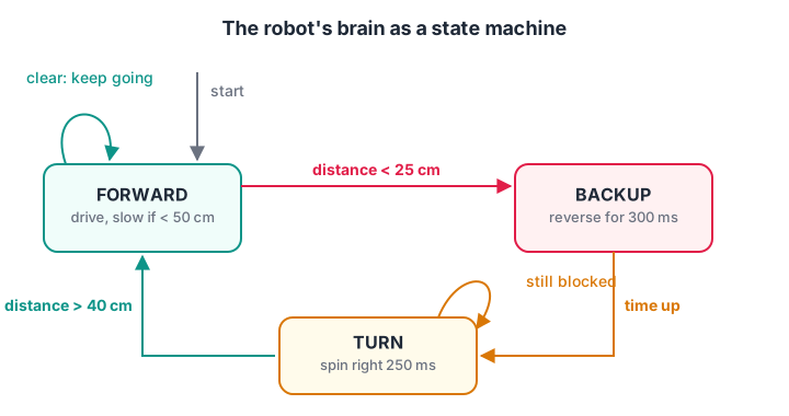
Distance thresholds and timers decide every move. The gap between 25 cm and 40 cm stops the robot flickering between states.
- FORWARD: drive at full speed when the path is clear, at reduced speed under 50 cm. If the distance drops below 25 cm, switch to BACKUP.
- BACKUP: reverse for 300 ms to make space for turning, then switch to TURN.
- TURN: spin on the spot for 250 ms, then look again. If the path is clearer than 40 cm, go back to FORWARD; otherwise turn again.
Using two different thresholds, 25 cm to stop and 40 cm to go, is called hysteresis. Without it, a robot sitting right at 25 cm would switch states on every noisy reading.
Quick check
Why does the robot use 25 cm to stop but 40 cm to start again?
Two thresholds create a dead band, so small reading changes near the limit do not trigger repeated switching.
The Arduino sketch
This complete sketch implements the state machine above. It uses millis() to time states instead of long delay() calls, so the sensor is read on every loop.
// Obstacle-avoiding robot: Arduino Uno + HC-SR04 + L298N
const int ENA = 5, IN1 = 7, IN2 = 8;     // left motor
const int ENB = 6, IN3 = 9, IN4 = 10;    // right motor
const int TRIG = 2, ECHO = 3;

const int STOP_CM = 25, CLEAR_CM = 40, SLOW_CM = 50;
const int FAST = 200, SLOW = 140, TURN_SPEED = 170;

enum State { FORWARD, BACKUP, TURN };
State state = FORWARD;
unsigned long stateStart = 0;

void setMotor(int en, int inA, int inB, int speed) {   // speed -255..255
  digitalWrite(inA, speed > 0 ? HIGH : LOW);
  digitalWrite(inB, speed < 0 ? HIGH : LOW);
  analogWrite(en, abs(speed));
}

void drive(int left, int right) {
  setMotor(ENA, IN1, IN2, left);
  setMotor(ENB, IN3, IN4, right);
}

long readDistanceCm() {
  digitalWrite(TRIG, LOW);
  delayMicroseconds(2);
  digitalWrite(TRIG, HIGH);
  delayMicroseconds(10);
  digitalWrite(TRIG, LOW);
  unsigned long us = pulseIn(ECHO, HIGH, 30000UL);  // give up after 30 ms
  if (us == 0) return 400;                           // no echo: treat as far
  return us * 0.0343 / 2;
}

void enter(State s) {
  state = s;
  stateStart = millis();
}

void setup() {
  int outputs[] = {ENA, IN1, IN2, ENB, IN3, IN4, TRIG};
  for (int pin : outputs) pinMode(pin, OUTPUT);
  pinMode(ECHO, INPUT);
  Serial.begin(9600);
  drive(0, 0);
  delay(2000);                 // time to put the robot on the floor
  enter(FORWARD);
}

void loop() {
  long d = readDistanceCm();
  unsigned long elapsed = millis() - stateStart;

  switch (state) {
    case FORWARD:
      if (d < STOP_CM)        { drive(0, 0); enter(BACKUP); }
      else if (d < SLOW_CM)   drive(SLOW, SLOW);
      else                    drive(FAST, FAST);
      break;
    case BACKUP:
      drive(-SLOW, -SLOW);
      if (elapsed >= 300) enter(TURN);
      break;
    case TURN:
      drive(TURN_SPEED, -TURN_SPEED);           // spin right on the spot
      if (elapsed >= 250) {
        if (d > CLEAR_CM) enter(FORWARD);
        else enter(TURN);                       // still blocked: turn again
      }
      break;
  }

  Serial.print(d);
  Serial.print(" cm  state=");
  Serial.println(state);
  delay(50);                   // let old echoes die out between pings
}
A few details worth knowing. pulseIn with a 30 ms timeout stops the code freezing if no echo returns.
The 50 ms delay at the end keeps pings far enough apart that a late echo from the previous ping is not mistaken for a new one. The motor speeds are PWM values from 0 to 255, explained in robot sensors and actuators.
Quick check
Why does the sketch use millis() for timing BACKUP and TURN instead of delay(300)?
Timing with millis() keeps the sense–think–act loop alive, so the robot never drives blind.
Simulate the decision logic in Python
Before you upload anything, you can check the logic with a list of fake sensor readings, one every 50 ms. This is the same state machine, written as a plain Python function, so you can test edge cases in seconds.
STOP_CM, CLEAR_CM, SLOW_CM = 25, 40, 50

def decide(state, d, elapsed):
    """Return (next_state, restart_timer, left_speed, right_speed)."""
    if state == "FORWARD":
        if d < STOP_CM:
            return "BACKUP", True, 0, 0
        speed = 140 if d < SLOW_CM else 200
        return "FORWARD", False, speed, speed
    if state == "BACKUP":
        if elapsed >= 300:
            return "TURN", True, 0, 0
        return "BACKUP", False, -140, -140
    if elapsed >= 250:                          # TURN finished: look again
        return ("FORWARD", True, 0, 0) if d > CLEAR_CM else ("TURN", True, 170, -170)
    return "TURN", False, 170, -170

# One fake ultrasonic reading every 50 ms
readings = [120, 90, 62, 48, 35, 22, 20, 23, 26, 30, 31, 32, 30, 28, 31, 33, 36, 34, 70, 95, 110, 115, 118]
state, entered = "FORWARD", 0
for i, d in enumerate(readings):
    t = i * 50
    nxt, restart, left, right = decide(state, d, t - entered)
    note = f"-> {nxt}" if restart else f"motors L={left:4} R={right:4}"
    print(f"t={t:4} ms  {d:3} cm  {state:7}  {note}")
    if restart:
        state, entered = nxt, t
Trace the output. The robot slows at 48 cm, switches to BACKUP at 22 cm, reverses for 300 ms, and turns. At 800 ms the first turn ends with only 36 cm of space, which is under the 40 cm "clear" threshold, so it turns again. By 1050 ms the path is open and it drives off at full speed.
Now try breaking it. Put a single reading of 5 in the middle of a clear run and see the robot back up for no reason. That is exactly what a stray echo does on real hardware, and it is why the next section suggests filtering.
Testing and debugging step by step
Test in small pieces rather than all at once.
- Sensor only. Upload a sketch that only prints the distance. Move your hand in front of it. Readings should change smoothly between roughly 3 cm and 2 m.
- Motors only, wheels in the air. Call
drive(150, 150)for two seconds, thendrive(-150, -150). Both wheels should spin forward, then backward. Swap motor wires if one is reversed. - Turning direction.
drive(170, -170)should spin the robot right. If it spins left, swap the left and right motor connections or flip the signs. - Full program on the floor. Start in an open space with a cardboard box as the obstacle, and keep the Serial Monitor open via a long USB cable or log states with the onboard LED.
If the robot resets when the motors start, the battery is weak or the grounds are poorly connected. If it ignores obstacles, check that ECHO is on D3 and the sensor is not tilted towards the floor.
If it stops at random, a stray reading is probably below 25 cm; take the median of three readings, as shown in the filtering section of the sensors article. If one side is faster, reduce the speed of the faster motor slightly in drive(); cheap gear motors are rarely identical.
When you want more problem-solving practice between builds, test your logic with quizzes on Debugshala Test.
Extensions to try next
- Scanning servo. Mount the HC-SR04 on an SG90 servo, look left and right during TURN, and turn towards the side with more space.
- Speed proportional to distance. Replace the two fixed speeds with a smooth function, a first taste of PID control.
- More sensors. Add IR sensors at the front corners to catch thin chair legs the ultrasonic beam misses.
- Wireless control. Swap the Uno for an ESP32 and add a phone web page to switch between manual and autonomous modes.
- Line plus obstacle. Combine IR line sensors with the ultrasonic sensor so the robot follows a track and stops for obstacles.
Key takeaways
- The project needs a chassis with two motors, an Arduino Uno, an L298N, an HC-SR04 and a battery, all sharing ground.
- A state machine with FORWARD, BACKUP and TURN keeps the behaviour readable and testable.
- Hysteresis and timers make the behaviour stable.
- Simulate the logic in Python first, then test hardware in small steps.
- Filtering, a scanning servo and extra sensors are the natural next upgrades.
FAQ
Why does my obstacle-avoiding robot keep hitting walls at an angle?
Ultrasonic sound reflects away from walls approached at a shallow angle, so no echo returns and the robot thinks the path is clear. Adding IR sensors at the corners, or a servo that scans left and right, solves most of these misses.
Can I build this robot with an ESP32 instead of an Arduino Uno?
Yes, but remember the ESP32 uses 3.3 V logic. Use a voltage divider on the HC-SR04's ECHO pin, choose output-capable GPIO pins for the driver, and use analogWrite (supported in the current Arduino ESP32 core) or the LEDC functions for PWM.
How long does the battery last?
It depends on your motors, cells and how often the robot stalls. A healthy pair of 18650 cells usually runs a small two-motor robot for a good while of continuous driving. Watch for slowing motors or resets, which are signs the cells need charging.
Where can I build an obstacle-avoiding robot with guidance in Indore?
Line-follower and obstacle-avoiding robots are core projects in the Robotics course at Debugshala, taught at the Old Palasia campus. You build them hands-on with Arduino, sensors and motor drivers, and the course ends with a final robot project. A free demo class lets you see the lab before you join.
From the team behind this site
Go further with the Robotics Course at Debugshala
These tutorials are written by Debugshala, a training and placement institute at Old Palasia, Indore. The classroom course adds live mentoring, real projects and interview preparation.
- Offline classes at Old Palasia, Indore
- Free demo class before you pay
- Non-IT, fresher and year-gap friendly
- Placement assistance
700+ students placed · 200+ hiring partners · 4.9★ Google rating
