

PID Control Explained: Tuning P, I and D for Robot Motors
PID control explained with a shower analogy, block diagram and Python motor simulation: what P, I and D do, tuning steps, windup and derivative kick.
You step into the shower on a January morning in Indore. The water is cold, so you turn the hot tap a lot. Nothing changes for a few seconds, because hot water takes time to travel through the pipe, so you turn it even more.
Suddenly the water is scalding. You yank the tap back, overshoot again, and spend the next minute swinging between too hot and too cold.
The next day you are smarter. You turn the tap in proportion to how cold the water feels. If it is still slightly cool after a while, you nudge it a little more. And when you feel the temperature rising quickly, you ease off before it gets too hot.
You just invented PID control. Those three habits, reacting to how wrong things are, to how long they have been wrong, and to how fast they are changing, are exactly the three terms in the most widely used controller in robotics.
What is a PID controller?
Map the shower onto a robot. The temperature you want is the setpoint. The temperature you feel is the measured value from a sensor. The difference is the error. Your hand on the tap is the controller output, for example a motor voltage. The pipe delay is the robot's dynamics: motors, wheels and arms cannot change speed instantly.
A PID controller is a feedback algorithm that sets an output from three terms, one proportional to the current error, one proportional to the accumulated error over time and one proportional to the rate of change of the error, to drive a system to its setpoint and hold it there.
In code, one update looks like this:
error      = setpoint - measured
integral   = integral + error * dt
derivative = (error - previous_error) / dt
output = Kp * error + Ki * integral + Kd * derivativeKp, Ki and Kd are the gains, numbers you choose. dt is the time between updates. That is the whole algorithm. The skill is in choosing the gains and handling the real-world edge cases.
The PID block diagram
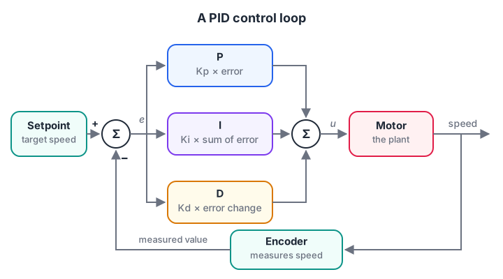
The error is split three ways, the terms are added into one command, and the sensor closes the loop.
This is the same sense–think–act loop from what is robotics, with the "think" step written as a formula. The encoder (covered in robot sensors and actuators) senses, the PID maths thinks, the motor acts, and the loop runs again every few milliseconds.
P, I and D: what each term does
P: proportional, the present
The P term pushes harder when the error is bigger. With Kp = 0.1 and a 90 degree error, the motor gets 9 volts; at 10 degrees it gets 1 volt. Raise Kp and the robot reacts faster, but too high and it overshoots and oscillates.
P has one stubborn weakness. If something constantly pushes back, such as gravity on an arm or friction on a wheel, the error can never reach zero, because zero error means zero output and then the load wins. The robot settles a little short. This leftover is called steady-state error.
I: integral, the past
The I term adds up the error over time. Even a small error, if it lasts, makes the integral grow until the output is strong enough to finish the job. That removes steady-state error. Too much Ki, though, and the integral keeps pushing after you arrive, causing overshoot.
D: derivative, the future
The D term looks at how fast the error is shrinking. If the robot is rushing towards the target, the error drops quickly, the derivative is large and negative, and D applies the brakes early.
It is the "ease off before it gets too hot" habit. D adds damping, but it also amplifies sensor noise, so keep Kd modest and filter the measurement if needed.
Quick check
Your robot always stops 3 cm short of the target and stays there. Which term fixes this?
A steady leftover error is what the integral term removes, by building up until the output overcomes the load.
Simulate a PID controller in Python
The simulation below models a motor turning a small arm from 0 to 90 degrees. The motor is limited to ±12 volts, has friction, and fights a constant load, like gravity on the arm. It prints the error every 0.2 seconds for four sets of gains. The structure is just a for loop with a few arithmetic lines.
def simulate(kp, ki, kd, setpoint=90.0, seconds=3.0, dt=0.005):
    angle, rate, integral, prev_error = 0.0, 0.0, 0.0, setpoint
    log = []
    for step in range(int(seconds / dt)):
        error = setpoint - angle                     # degrees still to go
        integral += error * dt
        derivative = (error - prev_error) / dt
        prev_error = error
        volts = kp * error + ki * integral + kd * derivative
        volts = max(-12.0, min(12.0, volts))         # battery limit
        # motor + arm model: torque from volts, friction, and a constant load
        rate += (1500 * volts - 3 * rate - 4000) * dt
        angle += rate * dt
        if step % 40 == 0:                           # log every 0.2 s
            log.append(error)
    return log

gains = {"P   Kp=0.1": (0.1, 0, 0),
         "PD  Kp=0.1 Kd=0.012": (0.1, 0, 0.012),
         "PID Kp=0.1 Ki=0.2 Kd=0.012": (0.1, 0.2, 0.012),
         "PID Ki too high (Ki=0.5)": (0.1, 0.5, 0.012)}
print("time (s)".ljust(27) + "".join(f"{t * 0.2:6.1f}" for t in range(15)))
for name, (kp, ki, kd) in gains.items():
    print(name.ljust(27) + "".join(f"{e:6.1f}" for e in simulate(kp, ki, kd)))
Read the output row by row:
- P only swings back and forth (the error even goes negative at 0.2 s, an overshoot) and is still wobbling 20 to 30 degrees short of the target after 3 seconds. The load wins the last part.
- PD stops the wobble almost immediately, which is D's damping at work, but it parks about 27 degrees short. D cannot fix steady-state error.
- PID closes the gap. A small overshoot of under 3 degrees appears at 0.6 s, and the error is essentially zero by about 2 seconds.
- Ki too high gets there faster at first, then overshoots by about 25 degrees before settling. More integral is not always better.
Change the gains and rerun. Try Kp=0.3 with no I or D and watch the oscillation get worse, then add Kd until it calms down.
Windup and derivative kick: two real-world traps
Integral windup
Real motors have limits. If the arm is jammed, or the target is far away, the output sits at the 12 volt limit while the integral keeps growing. When the robot finally moves, that huge stored integral keeps the output maxed out long after it should back off, and the robot overshoots badly. This is integral windup.
The simplest fix is clamping: stop adding to the integral while the output is saturated. The demo below jams the arm for 1.5 seconds and compares both versions.
def run(anti_windup, kp=0.1, ki=0.2, kd=0.012, dt=0.005):
    angle, rate, integral, prev_error = 0.0, 0.0, 0.0, 90.0
    peak = 0.0
    for step in range(int(4.0 / dt)):
        stuck = step * dt < 1.5                      # arm jammed for 1.5 s
        error = 90.0 - angle
        derivative = (error - prev_error) / dt
        prev_error = error
        trial = integral + error * dt
        raw = kp * error + ki * trial + kd * derivative
        volts = max(-12.0, min(12.0, raw))
        if not anti_windup or raw == volts:          # clamp: stop integrating
            integral = trial                         # while saturated
        if stuck:
            rate = 0.0
        else:
            rate += (1500 * volts - 3 * rate - 4000) * dt
            angle += rate * dt
        peak = max(peak, angle)
        if step % 100 == 0 and step:
            print(f"  t={step * dt:3.1f}s angle={angle:6.1f}  integral={integral:7.1f}")
    print(f"  peak angle {peak:.1f} deg (target 90)\n")

print("Without anti-windup:"); run(False)
print("With clamping anti-windup:"); run(True)
Without protection, the integral climbs to about 135 during the jam and the arm swings past 300 degrees once released. With clamping, the integral stops near 15 and the peak stays around 110 degrees. On a real robot arm, that difference is the gap between a smooth recovery and a broken bracket.
Derivative kick
If you suddenly change the setpoint, say from 90 to 120 degrees, the error jumps by 30 in a single update.
Divided by a dt of 0.005 seconds, the derivative becomes 6,000, and with Kd = 0.012 the D term alone asks for 72 volts for one step. The output slams to its limit for no good reason. This spike is called derivative kick.
The standard fix is to take the derivative of the measurement instead of the error: derivative = -(measured - previous_measured) / dt. When the setpoint is constant this gives exactly the same value, but a setpoint jump no longer produces a spike, because the robot itself has not moved yet.
Quick check
What causes derivative kick?
The jump divided by a small dt creates a huge derivative; taking the derivative of the measurement avoids it.
PID tuning tips that work in practice
- Start with I and D at zero. Increase Kp until the robot responds briskly and just starts to oscillate, then back off to about half.
- Add D to calm the overshoot. Increase it in small steps; if the motor starts buzzing or jittering, D is amplifying noise.
- Add a little I to remove steady-state error. Increase it until the error disappears in an acceptable time, and stop before overshoot grows.
- Change one gain at a time and keep notes of what each change did.
- Run the loop at a steady rate. A PID tuned at 100 Hz behaves differently at an irregular 30 Hz. Use the real
dtif timing varies. - Always add output limits and anti-windup before testing on real hardware.
You can practise this kind of reasoning with logic and coding questions on Debugshala's free practice tests before you tune real motors.
Common PID mistakes
- Wrong sign. If the error is defined backwards, the controller pushes the robot away from the target. Check the direction with a tiny Kp first.
- No output limit. The code asks for 50 volts and you get confusing behaviour at the hardware limit.
- Forgetting windup. Jams and long moves store a huge integral.
- Huge Kd on noisy sensors. Noise gets amplified into a shaking motor.
- Tuning on a stand, running on the floor. Load changes the dynamics, so do the final tuning in real conditions.
Key takeaways
- PID output = Kp × error + Ki × accumulated error + Kd × rate of change of error.
- P gives the push, I removes steady-state error, D damps overshoot.
- Tune in order: P, then D, then a little I, one change at a time.
- Clamp the output and the integral to avoid windup.
- Differentiate the measurement, not the error, to avoid derivative kick.
FAQ
Do I always need all three PID terms?
No. Many systems work with P alone, PI or PD. Speed control often uses PI, line followers often use PD, and position control against a constant load usually needs the full PID. Add a term only when the behaviour shows you need it.
How often should a PID loop run on an Arduino?
Fast enough that the robot barely changes between updates. For small wheeled robots, 50 to 200 updates per second is a common range. Use millis() or micros() to run it at a steady rate instead of relying on delay().
Is PID used in real industrial robots and drones?
Yes. PID and its variants control motor speed and position in industrial arms, CNC machines, quadcopter flight controllers, and temperature in ovens and 3D printers. Advanced robots often layer other controllers on top, but PID loops are usually running underneath.
Where can I practise PID on real robots in Indore?
A mentor-guided robotics course at Debugshala's Old Palasia campus has you build line-follower and obstacle-avoiding robots with DC motors and motor drivers, which is exactly where PID tuning becomes real. The course is project-based, and you can attend a free demo class before deciding.
From the team behind this site
Go further with the Robotics Course at Debugshala
These tutorials are written by Debugshala, a training and placement institute at Old Palasia, Indore. The classroom course adds live mentoring, real projects and interview preparation.
- Offline classes at Old Palasia, Indore
- Free demo class before you pay
- Non-IT, fresher and year-gap friendly
- Placement assistance
700+ students placed · 200+ hiring partners · 4.9★ Google rating
