

IMU Sensor Fusion: Accelerometer, Gyroscope and Filters in Python
Learn IMU sensor fusion: get tilt from an accelerometer, calibrate gyro drift, tune a complementary filter and read an MPU-6050 on Arduino, with Python code.
Imagine you are standing in a crowded Indore city bus with your eyes closed. Your inner ear tells you instantly when the bus swerves, but after ten minutes you have no idea which way you are facing.
Your feet, on the other hand, always know which way is down, yet every time the driver brakes you feel as if the floor has tilted.
You never actually get lost, because your brain blends the two. It trusts the inner ear for quick changes and the steady pull of gravity through your feet for the long-term picture.
A robot faces exactly the same problem, and it solves it in exactly the same way.
What is an IMU and what is sensor fusion?
Map the bus ride onto a robot. Your inner ear is the gyroscope: fast, smooth, but drifting over time. Your feet sensing gravity are the accelerometer: right on average, but fooled whenever the robot speeds up or brakes. Your brain blending the two is the sensor fusion algorithm.
An IMU is an electronic sensor that measures a body's acceleration and rotation rate, and sensor fusion is the technique of combining several imperfect sensor readings into one estimate that is better than any of them alone.
Self-balancing robots, drones, robot vacuums and phones all depend on this. In the previous lesson on wheel encoders and odometry you saw that wheel counts alone drift on every turn. An IMU is the usual second opinion on which way the robot is pointing.
The sensors and actuators overview showed a first complementary filter. This article goes deeper: the maths behind tilt, gyroscope calibration, how to tune the filter, and real MPU-6050 code.
What does each IMU sensor measure?
| Sensor | Measures | Unit | Strength | Weakness |
|---|---|---|---|---|
| Accelerometer | Acceleration along X, Y, Z, including gravity | g or m/s² | Knows which way is down, never drifts | Noisy, and any real motion looks like tilt |
| Gyroscope | Rotation rate around X, Y, Z | degrees per second | Smooth, fast, ignores vibration and motion | Small bias makes the integrated angle drift |
| Magnetometer | Earth's magnetic field along X, Y, Z | microtesla | Gives an absolute compass heading (yaw) | Distorted by motors, batteries and steel frames |
A 6-axis IMU such as the MPU-6050 has the first two. A 9-axis IMU adds the magnetometer. The three rotation angles you care about are roll (tipping sideways), pitch (nose up or down) and yaw (turning left or right).
How to get tilt from an accelerometer
When the robot is still, the only acceleration the chip feels is gravity, 1 g pointing down. If you tilt it, that 1 g gets shared between the axes, and trigonometry turns the shares back into angles:
- roll = atan2(ay, az)
- pitch = atan2(−ax, √(ay² + az²))
The MPU-6050 reports raw 16-bit numbers. In its default ±2 g range, 16,384 counts equal 1 g, so you divide before using the formulas.
import math

LSB_PER_G = 16384.0          # MPU-6050 default ±2 g range

def tilt(ax_raw, ay_raw, az_raw):
    ax, ay, az = ax_raw / LSB_PER_G, ay_raw / LSB_PER_G, az_raw / LSB_PER_G
    roll = math.degrees(math.atan2(ay, az))
    pitch = math.degrees(math.atan2(-ax, math.sqrt(ay * ay + az * az))) + 0.0
    return roll, pitch

cases = {
    "flat on the table":       (0, 0, 16384),
    "tipped 30 deg sideways":  (0, 8192, 14189),
    "flat, braking at 0.3 g":  (-4915, 0, 16384),
}
for name, raw in cases.items():
    r, p = tilt(*raw)
    print(f"{name:24} roll={r:6.1f} deg  pitch={p:6.1f} deg")
The first two rows are correct. The third is the trap: the robot is perfectly flat, but because it is braking, the accelerometer reports about 17 degrees of pitch. A balancing robot that believed this reading would throw itself forward.
Quick check
A robot is flat but accelerating forward. What happens to the pitch computed from the accelerometer?
An accelerometer senses all acceleration, not just gravity, so linear motion appears as tilt. That is why the gyroscope is trusted for short-term changes.
Why gyroscopes drift, and how to calibrate them
A gyroscope tells you how fast you are rotating, so to get an angle you add up rate × time on every loop. That is integration, and it has a weakness: any constant offset in the reading, called bias, is added every loop too.
A bias of just 1.8 degrees per second sounds tiny, but after one minute it becomes over 100 degrees of imaginary rotation. The fix is simple: keep the robot still at power-up, average a few hundred gyro readings, and subtract that average from every later reading.
import numpy as np
rng = np.random.default_rng(7)

dt = 0.01                                   # 100 Hz
bias = 1.8                                  # deg/s, unknown to the robot
still = bias + rng.normal(0, 0.4, 300)      # 3 s of readings while still
est_bias = still.mean()
print(f"estimated bias: {est_bias:.3f} deg/s (true {bias})")

readings = bias + rng.normal(0, 0.4, 6000)  # robot stays still for 60 s
raw_angle = np.cumsum(readings * dt)
cal_angle = np.cumsum((readings - est_bias) * dt)
for t in (10, 30, 60):
    i = int(t / dt) - 1
    print(f"after {t:2d} s  raw drift {raw_angle[i]:7.2f} deg   calibrated {cal_angle[i]:6.2f} deg")
Calibration shrinks the drift from over a hundred degrees a minute to about three. It cannot remove drift completely, because the estimate is never perfect and bias also changes slowly with temperature. That leftover drift is what sensor fusion cleans up.
How does a complementary filter fuse the two?
The two sensors fail in opposite ways. The gyroscope is good over short times and bad over long ones. The accelerometer is bad over short times and good over long ones. So you take the high-frequency part of the gyro angle and the low-frequency part of the accelerometer angle, and add them.
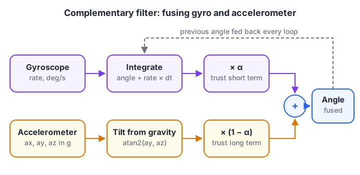
Each sensor contributes only the part of the signal it is good at, and the weights always add up to 1.
In code this is one line, run every loop:
angle = α × (angle + gyro_rate × dt) + (1 − α) × accel_angle
Choosing alpha from a time constant
You will often see "use 0.98", but alpha only means something together with your loop time. A better way is to choose a time constant τ in seconds, roughly how long you trust the gyroscope before leaning on gravity, then compute α = τ / (τ + dt).
At 100 Hz (dt = 0.01 s), α = 0.98 gives τ of about 0.5 s. If you later speed the loop up to 500 Hz and keep 0.98, your filter quietly changes behaviour. The block below tests four time constants on a robot that brakes hard for half a second while a gyro bias is left over.
import numpy as np
rng = np.random.default_rng(3)

dt, n = 0.01, 1500                                   # 15 s at 100 Hz
t = np.arange(n) * dt
true = 5 * np.sin(0.8 * t)                           # real pitch, degrees
gyro = np.gradient(true, dt) + 0.6 + rng.normal(0, 0.3, n)   # leftover bias 0.6 deg/s
accel = true + rng.normal(0, 2.0, n)
accel[(t > 6) & (t < 6.5)] += 15                     # hard braking fools the accelerometer

for tau in (0.05, 0.5, 2.0, 20.0):
    a = tau / (tau + dt)
    angle, est = accel[0], []
    for i in range(n):
        angle = a * (angle + gyro[i] * dt) + (1 - a) * accel[i]
        est.append(angle)
    err = np.abs(np.array(est) - true)
    brake = (t > 6) & (t < 7)
    print(f"tau={tau:5.2f}s alpha={a:.4f}  normal driving err={err[~brake].mean():4.2f}  "
          f"worst braking err={err[brake].max():5.2f} deg")
Read the two error columns together. A tiny τ copies the noisy accelerometer and swallows almost the whole braking spike. A huge τ shrugs off braking but lets the leftover gyro bias pull the angle away during normal driving. Values between about 0.5 and 2 seconds balance both, which suits most small ground robots.
Quick check
Your loop runs at 200 Hz (dt = 0.005 s) and you want a complementary filter time constant of 0.5 s. What alpha should you use?
alpha = tau / (tau + dt) = 0.5 / 0.505, which is about 0.990. Using 0.98 would give a shorter time constant of about 0.25 s.
Reading an MPU-6050 on Arduino
The MPU-6050 talks over I2C at address 0x68. You wake it by writing 0 to its power management register (0x6B), then read 14 bytes starting at register 0x3B: three accelerometer axes, temperature, and three gyroscope axes, each as a high byte then a low byte.
#include <Wire.h>
const uint8_t MPU = 0x68;
float gyroBiasX = 0, angle = 0;
unsigned long last;

void readRaw(int16_t v[7]) {
  Wire.beginTransmission(MPU); Wire.write(0x3B); Wire.endTransmission(false);
  Wire.requestFrom(MPU, (uint8_t)14);
  for (int i = 0; i < 7; i++) v[i] = (Wire.read() << 8) | Wire.read();
}

void setup() {
  Serial.begin(115200);
  Wire.begin();
  Wire.beginTransmission(MPU); Wire.write(0x6B); Wire.write(0); Wire.endTransmission();
  int16_t v[7];
  for (int i = 0; i < 300; i++) { readRaw(v); gyroBiasX += v[4] / 131.0; delay(3); }
  gyroBiasX /= 300;                       // keep the robot still during this
  last = micros();
}

void loop() {
  int16_t v[7]; readRaw(v);
  float dt = (micros() - last) / 1e6; last = micros();
  float ay = v[1] / 16384.0, az = v[2] / 16384.0;
  float accelRoll = atan2(ay, az) * 180.0 / PI;
  float gyroX = v[4] / 131.0 - gyroBiasX;  // deg/s, ±250 range
  float tau = 0.5, a = tau / (tau + dt);
  angle = a * (angle + gyroX * dt) + (1 - a) * accelRoll;
  Serial.println(angle);
  delay(10);
}
Two details matter. The loop measures the real dt with micros() instead of assuming it, and the alpha is recomputed from τ each time, so the filter stays consistent even when the loop timing wobbles. The same register map works on an ESP32 with its default I2C pins.
What about yaw? Magnetometers and better filters
Gravity says nothing about which compass direction you face, so the accelerometer cannot correct yaw. Your options are a magnetometer, a camera or lidar that recognises the surroundings, or simply accepting slow yaw drift and correcting it with wheel odometry.
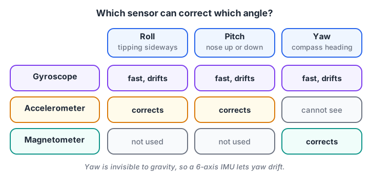
The gyroscope drives every angle in the short term; each slow sensor can only anchor the angles it can physically observe.
For full 3D orientation, robots use stronger fusion algorithms:
| Algorithm | Idea | Typical use |
|---|---|---|
| Complementary filter | Fixed blend of gyro and accelerometer | Balancing robots, hobby drones, roll and pitch |
| Madgwick or Mahony filter | Gradient or feedback correction using quaternions | 9-axis orientation on microcontrollers |
| Kalman filter (EKF) | Weights each sensor by its measured noise, updated every step | Drones, vehicles, ROS 2 robot_localization |
The Kalman filter is the most general of these, and it is the subject of the next lesson, Kalman filter explained. Some newer IMU chips even run fusion on board and output orientation directly.
Common mistakes with IMUs
- Skipping gyro calibration. Always average the bias while the robot is still, and tell users not to move it during start-up.
- Mounting the IMU loosely or far from the centre. Vibration and spinning add fake acceleration. Mount it firmly, close to the centre of rotation.
- Mixing up axes. Check which way X, Y and Z point on your board by tilting it slowly and printing raw values.
- Using a fixed alpha with a changing loop rate. Derive alpha from τ and the real
dt. - Trusting a magnetometer near motors. Calibrate it in place and keep it away from current-carrying wires.
- Forgetting units. atan2 returns radians; gyroscopes usually report degrees per second.
Key takeaways
- An IMU combines an accelerometer, a gyroscope and sometimes a magnetometer.
- Accelerometer tilt uses atan2 and is only correct when the robot is not accelerating.
- Gyro angles drift because bias is integrated; calibrate the bias at start-up.
- A complementary filter blends gyro (short term) with accelerometer (long term); pick its time constant, then compute alpha.
- Yaw needs a magnetometer or another external reference. Kalman and Madgwick filters handle full 3D orientation.
FAQ
What is sensor fusion in robotics?
Sensor fusion in robotics is combining readings from several sensors so the result is more accurate and reliable than any single sensor. A common example is merging gyroscope and accelerometer data into a stable tilt angle, or merging wheel odometry with an IMU to track position.
What is the difference between a 6-axis and a 9-axis IMU?
A 6-axis IMU contains a 3-axis accelerometer and a 3-axis gyroscope, so it can estimate roll and pitch well but yaw only drifts. A 9-axis IMU adds a 3-axis magnetometer, which gives an absolute compass heading and lets the fusion correct yaw drift too.
Is a complementary filter as good as a Kalman filter?
For roll and pitch on a small robot, a well-tuned complementary filter is often nearly as good and far simpler. A Kalman filter wins when sensor noise changes, when you fuse many sensors, or when you need uncertainty estimates for later steps such as localisation.
Why does my MPU-6050 angle keep drifting?
The usual causes are an uncalibrated gyroscope bias, a wrong dt in the integration, or relying on the gyroscope alone. Average the gyro output while still, measure the loop time with micros(), and blend in the accelerometer angle with a complementary filter.
Can I learn IMU and sensor projects in Indore?
Yes. You can learn sensor wiring hands-on at Debugshala, whose project-based robotics course at the Old Palasia campus covers Arduino, ESP32, motion and distance sensors, and robot builds, taught in English and Hindi with a free demo class. To revise the Python side, work through quick MCQs on Debugshala Test.
From the team behind this site
Go further with the Robotics Course at Debugshala
These tutorials are written by Debugshala, a training and placement institute at Old Palasia, Indore. The classroom course adds live mentoring, real projects and interview preparation.
- Offline classes at Old Palasia, Indore
- Free demo class before you pay
- Non-IT, fresher and year-gap friendly
- Placement assistance
700+ students placed · 200+ hiring partners · 4.9★ Google rating
