

Line Follower Robot Project: Arduino, IR Sensors and PD Control
Build a line follower robot with Arduino, five IR sensors and a TB6612FNG: wiring, calibration, a PD control sketch and a Python sim for tuning Kp and Kd.
Picture a new delivery rider told to follow the yellow lane markings on a service road. On a straight stretch he barely touches the handlebar. When the paint curves, he leans a little. When he drifts badly, he leans hard, and he learns not to over-correct, or he snakes from edge to edge.
He keeps answering one question: how far am I from the line, and which way? A line follower robot asks the same question about a hundred times a second, using a row of infrared sensors a few millimetres above the floor.
What is a line follower robot?
Map the rider onto the robot. His glance at the paint becomes the IR sensor array. His sense of "a bit left of centre" becomes a single number, the line position. How hard he leans becomes the correction your controller calculates. The handlebar becomes the difference in speed between the two wheels.
A line follower robot is an autonomous mobile robot that detects a contrasting line on the floor with reflectance sensors and continuously adjusts its left and right wheel speeds so the line stays under its centre.
It is the natural project after the obstacle-avoiding robot. That robot made yes-or-no decisions from one sensor; this one makes smooth, proportional decisions from five.
How does an IR line sensor see a black line?
Each TCRT5000 module has an infrared LED and a phototransistor side by side. White paper reflects most of the light back and black tape absorbs most of it, so the module's analog pin reads differently over each. On most modules the reading rises over black; if yours works the other way round, you flip one setting in the sketch.
Quick check
Your robot follows the line but snakes from side to side. What is the usual first fix?
Snaking is overshoot. The derivative term damps it, and a lower Kp reduces how hard each correction is.
Parts list for the line follower
| Part | Quantity | Notes |
|---|---|---|
| 2WD chassis with two geared DC motors, wheels and a caster | 1 | Low and light is better than big and heavy |
| Arduino Uno or compatible board | 1 | Analog pins A0–A4 read the sensors |
| TCRT5000 IR modules with an analog (AO) pin | 5 | Or one 5-channel analog array |
| TB6612FNG dual motor driver module | 1 | More efficient than an L298N with small motors |
| 2 × 18650 Li-ion cells, holder and switch | 1 set | About 7.4 V for the motors |
| Small buck converter set to 5.0 V | 1 | Powers the Arduino and sensors from the battery |
| Black electrical tape (18–20 mm wide) and white chart paper | 1 roll | Your first track |
| Jumper wires, screws, standoffs | As needed | Mount the sensors 3–8 mm above the floor |
Wiring the robot
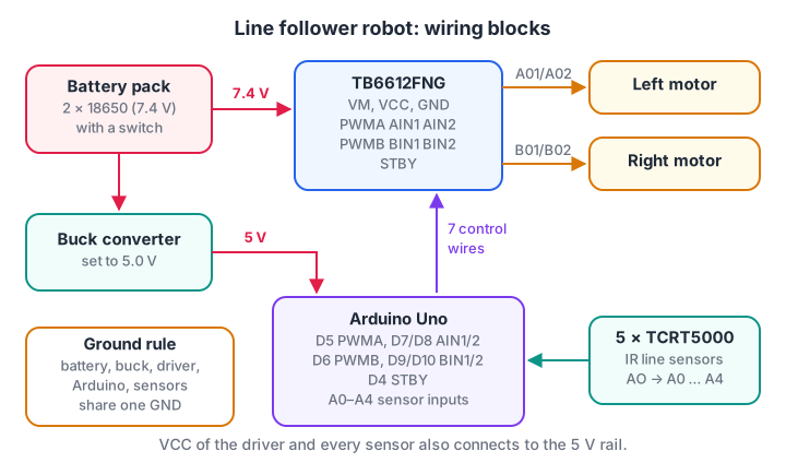
Motor power and logic power are separated by the buck converter, but every ground is joined.
- Set the buck converter first. Adjust it until a multimeter reads 5.0 V at its output, then connect it to the Arduino's 5V pin.
- Motor power. Battery positive through the switch to the driver's VM pin, battery negative to GND. The driver's VCC pin goes to the 5 V rail.
- Motors. Left motor to A01/A02, right motor to B01/B02.
- Control pins. PWMA → D5, AIN1 → D7, AIN2 → D8, PWMB → D6, BIN1 → D9, BIN2 → D10, STBY → D4.
- Sensors. VCC to 5 V, GND to ground, and AO pins to A0 (far left) through A4 (far right), about 15 mm apart in a row at the front.
How do five sensors become one steering number?
Checking five sensors one by one leads to a fragile chain of if statements. A better method is a weighted average. Give each sensor a weight from 0 (far left) to 4000 (far right) in steps of 1000, multiply each calibrated reading by its weight, add them up and divide by the total reading.
The result is the line's position under the robot, from 0 to 4000. A centred line gives about 2000, so the error is simply position − 2000. Negative means the line is to the left, positive means it is to the right.
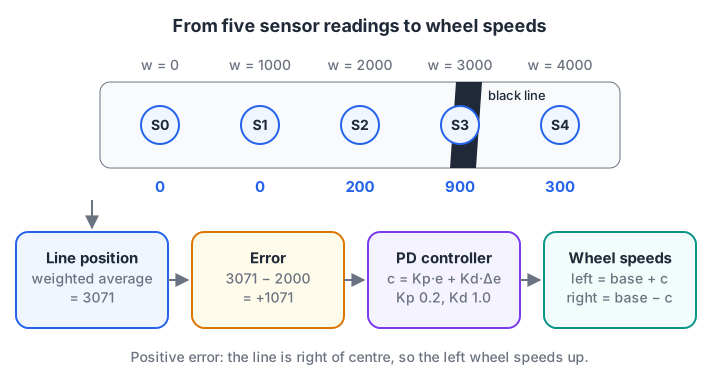
The sensor row produces one error number, and the PD controller turns that into a speed difference between the wheels.
Try the arithmetic yourself before you trust it on hardware.
def line_position(vals):
    """Weighted average of 5 calibrated readings (0 = white, 1000 = black)."""
    total = sum(vals)
    if total == 0:
        return None                      # no sensor sees the line
    return sum(v * i * 1000 for i, v in enumerate(vals)) // total

samples = {
    "line centred":         [0, 150, 1000, 150, 0],
    "line slightly right":  [0, 0, 700, 600, 0],
    "line far left":        [900, 300, 0, 0, 0],
    "off the track":        [0, 0, 0, 0, 0],
}
for name, vals in samples.items():
    pos = line_position(vals)
    if pos is None:
        print(f"{name:20} -> line lost, use the last known side")
    else:
        print(f"{name:20} -> position {pos:4}, error {pos - 2000:+5}")
Why use PD instead of simple on-off steering?
On-off steering turns hard whenever an edge sensor sees black. It works, but it wobbles and has to crawl. A proportional term steers in proportion to the error, and a derivative term reacts to how fast the error is changing, pushing back before the robot overshoots.
Line followers usually skip the integral term, because the curving track leaves little steady error to remove. The theory is in PID control explained.
Quick check
The calibrated readings are [0, 0, 300, 900, 0]. Which way is the line, and which wheel should speed up?
The weighted position is about 2750, so the error is positive. The line is to the right, so the left wheel speeds up to turn the robot right.
The Arduino sketch
This sketch calibrates by spinning over the line for three seconds, then runs a PD loop every 10 ms.
// Line follower: Arduino Uno + 5 x TCRT5000 (analog) + TB6612FNG
const int SENSOR_PINS[5] = {A0, A1, A2, A3, A4};   // A0 = far left
const int PWMA = 5, AIN1 = 7, AIN2 = 8;            // left motor
const int PWMB = 6, BIN1 = 9, BIN2 = 10;           // right motor
const int STBY = 4;
const bool BLACK_READS_HIGH = true;    // set false if your modules read low on black

float Kp = 0.2, Kd = 1.0;              // starting values, tune on your track
int baseSpeed = 150;
int minV[5], maxV[5];
int lastError = 0;

void setMotor(int pwm, int in1, int in2, int speed) {
  speed = constrain(speed, -255, 255);
  digitalWrite(in1, speed > 0 ? HIGH : LOW);
  digitalWrite(in2, speed < 0 ? HIGH : LOW);
  analogWrite(pwm, abs(speed));
}

void drive(int left, int right) {
  setMotor(PWMA, AIN1, AIN2, left);
  setMotor(PWMB, BIN1, BIN2, right);
}

void calibrate() {
  for (int i = 0; i < 5; i++) { minV[i] = 1023; maxV[i] = 0; }
  unsigned long start = millis();
  drive(110, -110);                    // spin slowly so every sensor crosses the line
  while (millis() - start < 3000) {
    for (int i = 0; i < 5; i++) {
      int v = analogRead(SENSOR_PINS[i]);
      minV[i] = min(minV[i], v);
      maxV[i] = max(maxV[i], v);
    }
  }
  drive(0, 0);
}

// Line position 0..4000, or -1 when no sensor sees the line
long readLine() {
  long weighted = 0, total = 0;
  for (int i = 0; i < 5; i++) {
    int span = max(maxV[i] - minV[i], 1);
    long v = (long)(analogRead(SENSOR_PINS[i]) - minV[i]) * 1000 / span;
    v = constrain(v, 0, 1000);
    if (!BLACK_READS_HIGH) v = 1000 - v;
    if (v < 150) v = 0;                // ignore the faint glow of a white floor
    weighted += v * i * 1000;
    total += v;
  }
  return total == 0 ? -1 : weighted / total;
}

void setup() {
  int outs[] = {PWMA, AIN1, AIN2, PWMB, BIN1, BIN2, STBY};
  for (int p : outs) pinMode(p, OUTPUT);
  digitalWrite(STBY, HIGH);            // take the driver out of standby
  Serial.begin(115200);
  delay(1000);
  calibrate();
  delay(1000);                         // place the robot on the line now
}

void loop() {
  long pos = readLine();
  if (pos < 0) {                       // line lost: spin towards where it was last seen
    if (lastError > 0) drive(130, -130);
    else drive(-130, 130);
  } else {
    int error = pos - 2000;            // positive = line is to the right
    int correction = Kp * error + Kd * (error - lastError);
    lastError = error;
    drive(baseSpeed + correction, baseSpeed - correction);
  }
  delay(10);                           // keep the loop period steady for the D term
}
The delay(10) matters: the derivative term compares this error with the last one, so if the loop period changes, the effective Kd changes too.
Simulate the robot and tune Kp and Kd in Python
Tuning on the floor is slow. A rough simulation gets you into the right range first. This one models an S-shaped track, five sensors, a 40 ms delay between reading and reacting, and motors that take about 80 ms to reach a new speed.
import math
line_y = lambda x: 0.10 * math.sin(x / 0.25)          # S-shaped track (metres)

def read_sensors(x, y, th):                            # 5 sensors, 15 mm apart, 60 mm ahead
    vals = []
    for i in range(5):                                 # sensor 0 is on the left
        off = (2 - i) * 0.015
        sx, sy = x + 0.06*math.cos(th) - off*math.sin(th), y + 0.06*math.sin(th) + off*math.cos(th)
        vals.append(max(0, int(1000 * (1 - abs(sy - line_y(sx)) / 0.02))))
    return vals

def run(kp, kd, base=150, dt=0.01):
    x = y = th = vl = vr = 0.0
    last, total, queue = 0, 0, [(0, 0)] * 4            # 40 ms delay from sensor to wheels
    for _ in range(500):                               # 5 seconds of driving
        v = read_sensors(x, y, th)
        if sum(v) == 0:                                # lost: spin towards last side seen
            err, corr = last, (130 if last > 0 else -130)
        else:
            err = sum(val * i * 1000 for i, val in enumerate(v)) // sum(v) - 2000
            corr = kp * err + kd * (err - last)
        last, total = err, total + abs(err)
        queue.append((max(-255, min(255, base + corr)), max(-255, min(255, base - corr))))
        left, right = queue.pop(0)
        vl += (left / 255 * 0.5 - vl) * dt / 0.08     # motors take ~80 ms to respond
        vr += (right / 255 * 0.5 - vr) * dt / 0.08
        th += (vr - vl) / 0.12 * dt                    # 12 cm between the wheels
        x, y = x + (vl + vr) / 2 * math.cos(th) * dt, y + (vl + vr) / 2 * math.sin(th) * dt
    return total // 500, round(x, 2)

for kp, kd in [(0.03, 0), (0.2, 0), (0.2, 1.0), (0.2, 4.0)]:
    mean, dist = run(kp, kd)
    print(f"Kp={kp:<5} Kd={kd:<4} mean |error| = {mean:5}   reached x = {dist} m in 5 s")
Read the rows as a story. A tiny Kp is lazy and drifts wide on curves. Kp = 0.2 without D overshoots and snakes, covering far less track in 5 seconds. Adding Kd = 1.0 damps the swing and gives the smallest error. Kd = 4.0 over-reacts to every small change and slows the robot again.
Your robot's numbers will differ, but the pattern holds. Change the delay to 8 steps and see how much harder tuning becomes; that is why a fast, steady loop matters.
Testing and debugging step by step
- Print raw sensor values. Slide white paper and black tape under each sensor. You want a clear gap, for example 80 on white and 700 on black.
- Check sensor order. Put the tape under the far-left sensor only. The calibrated position should be close to 0. If it is near 4000, your wires are reversed.
- Check motor direction with the wheels lifted.
drive(150, 150)should spin both wheels forward. Swap a motor's two wires if one runs backwards. - Tune P first. With Kd at 0 and baseSpeed at 120, raise Kp until the robot starts to wobble, then back off a little.
- Add D. Increase Kd in steps of 0.5 until the wobble disappears. Only then raise baseSpeed.
If it loses the line on sharp bends, lower baseSpeed or move the sensors further ahead of the wheels. If readings change with room lighting, shield the sensors with black card. If it spins forever after losing the line, check that lastError is not being reset to zero.
Want to keep your logic sharp between tuning sessions? Solve logic MCQs between builds on Debugshala Test.
Common mistakes
- Skipping calibration. Uncalibrated sensors give a biased position, so the robot hugs one edge of the line.
- Mounting sensors too high. Above about 10 mm the IR spot blurs and neighbouring sensors see the same patch.
- Changing two gains at once. Adjust one number per run and write it down.
Extensions to try next
- Junction detection. When all five sensors read black, you have hit a cross line. Count crossings to follow a route.
- Line plus obstacle. Add the HC-SR04 from the previous project and stop when something blocks the track.
- Wireless tuning. Send new Kp and Kd values from your phone, which the next project, the Bluetooth controlled robot, makes easy.
- Encoders. Add wheel encoders to measure real speed, covered in wheel encoders and odometry.
Key takeaways
- Five analog IR sensors give a smooth line position from 0 to 4000 through a weighted average.
- The error from the centre drives a PD controller, and the result becomes a difference between the wheel speeds.
- Calibrate every sensor, keep the loop period steady, and remember the last side the line was seen.
- Tune Kp first with Kd at zero, then add Kd to remove wobble, then raise speed.
- A simple Python simulation shows how gains and delays change the robot's behaviour before you touch hardware.
FAQ
How many sensors does a line follower robot need?
Two sensors are enough for a slow robot with on-off steering. Three to five analog sensors work much better because they give a graded position that a PD controller can use. More than eight rarely helps a beginner robot.
Why does my line follower work on one track but not another?
Different tapes, papers and lighting reflect different amounts of infrared light. Recalibrate on each new surface, keep the sensors at a fixed height, and avoid shiny tape, which can reflect almost as much as white paper.
Can I use an L298N instead of a TB6612FNG?
Yes. The L298N uses the same idea, one PWM and two direction pins per motor, so only the pin names change. It drops roughly 2 V internally and runs warm, so your motors are slower on the same battery.
Should a line follower use PID or just PD?
Most line followers use PD. The track keeps curving, so a constant offset rarely builds up, and an integral term tends to wind up on long curves. Add a small Ki only if the robot stays off-centre on long straights.
Where can I learn to build a line follower robot in Indore?
The line follower is a core build in Debugshala's line-follower and PID lab sessions in Indore, part of its project-based Robotics course at the Old Palasia campus. You wire sensors and drivers, tune on a real track and finish with a final robot project. A free demo class comes first.
From the team behind this site
Go further with the Robotics Course at Debugshala
These tutorials are written by Debugshala, a training and placement institute at Old Palasia, Indore. The classroom course adds live mentoring, real projects and interview preparation.
- Offline classes at Old Palasia, Indore
- Free demo class before you pay
- Non-IT, fresher and year-gap friendly
- Placement assistance
700+ students placed · 200+ hiring partners · 4.9★ Google rating
