

Robotic Arm Project: Build a 4-DOF Servo Arm with Arduino
Build a 4-DOF robotic arm with Arduino, PCA9685 and servos: wiring, safe joint limits, teach-and-playback code and inverse kinematics in Python.
Watch a tailor in a Sarafa lane shop cutting cloth. His shoulder swings his whole arm over the table, his elbow decides how far he reaches, his wrist sets the angle, and his fingers pinch the fabric. He never thinks about angles. He thinks "put the scissors there", and his joints sort it out.
A desktop robotic arm has the same four jobs and none of the tailor's instinct. First you will set its angles directly, with a knob per joint. Then you will teach it to work out the angles from a target point, as the tailor's brain does.
What is a robotic arm?
Map the tailor onto the robot. His shoulder swing is the base servo turning the arm left and right. His upper arm and forearm are two links moved by the shoulder and elbow servos. His fingers are the gripper servo. His "put the scissors there" is inverse kinematics: turning a position into joint angles.
A robotic arm is a chain of rigid links connected by motorised joints, controlled so that its end effector, such as a gripper, reaches a desired position and orientation in space.
Industrial arms have six joints and precise motors with encoders. Your four hobby servos are plenty to learn the key ideas: joint limits, smooth motion, teach-and-repeat and kinematics. New to servos? Read servo motors with Arduino first.
Parts list and wiring
| Part | Quantity | Notes |
|---|---|---|
| 4-DOF acrylic or 3D-printed desktop arm kit | 1 | Base, shoulder, elbow and gripper joints |
| MG90S metal-gear micro servos | 4 | Plastic-gear SG90s strip easily under load |
| Arduino Uno | 1 | |
| PCA9685 16-channel PWM servo driver | 1 | Controlled over I2C, frees the Arduino from servo timing |
| 5 V power supply rated 3 A or more | 1 | Powers the servos only |
| 10 kΩ potentiometers with knobs | 4 | One per joint for manual control |
| Push buttons | 2 | Record and play |
| Jumper wires, breadboard | As needed |
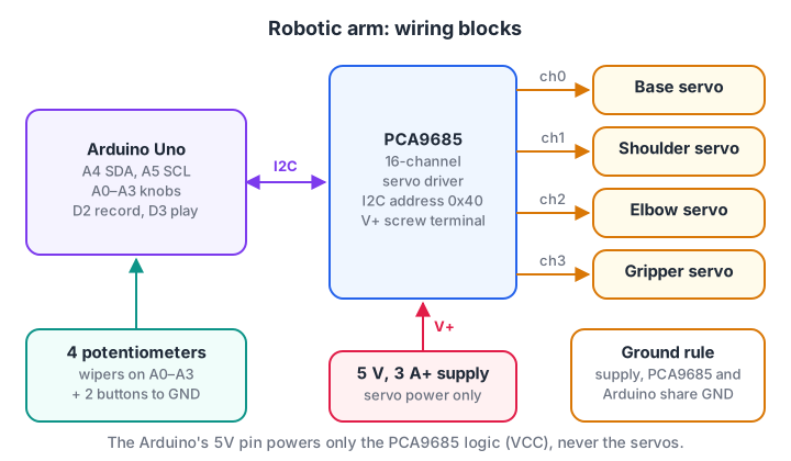
The Arduino only sends I2C messages; the PCA9685 generates all four servo signals, and the servos get their own power.
- I2C. PCA9685 SDA → A4, SCL → A5, VCC → Arduino 5V, GND → GND.
- Servo power. The 5 V supply goes to the PCA9685's green screw terminal (V+ and GND), never to the Arduino's 5V pin.
- Servos. Base on channel 0, shoulder on 1, elbow on 2, gripper on 3. Brown or black wire goes to GND on the header.
- Potentiometers. Outer pins to 5V and GND, middle pins to A0 (base) through A3 (gripper).
- Buttons. Record between D2 and GND, play between D3 and GND. The sketch uses internal pull-ups.
Set the servo limits before assembly
Hobby servos turn roughly 180°, but your arm's joints usually cannot. If the frame stops the elbow at 20° and the code asks for 0°, the servo stalls, heats up and strips its gears. Centre every servo at 90° before fitting the horns, then move each joint slowly and note the safe minimum and maximum for MIN_DEG and MAX_DEG.
Quick check
Why should servos be powered from a separate 5 V supply rather than the Arduino's 5V pin?
Servo current spikes, especially when stalled, pull the supply down. A dedicated supply with a shared ground keeps the logic stable.
How does teach-and-playback work?
Teach-and-playback is how many factory arms are still programmed: an operator moves the arm with a handheld pendant, records each key pose, and the robot repeats the sequence.
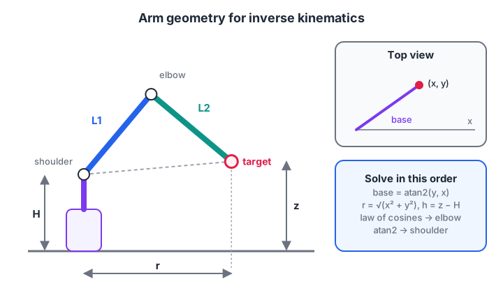
Two links and two angles place the gripper in the vertical plane; the base angle turns that plane to face the target.
In this project the four knobs are the pendant. Each loop does four things:
- Read targets. Each knob sets one joint's target within its safe range, or, in playback, targets come from saved poses.
- Step towards the target. Each joint moves at most 2° per 20 ms, so even a fast knob spin gives smooth motion.
- Write the servos. Angles become 500–2500 µs pulses sent to the PCA9685.
- Handle buttons. Record saves the current targets as a pose. Play toggles playback, which advances when every joint has arrived.
The Arduino sketch
Install the Adafruit PWM Servo Driver library from the Library Manager first.
// 4-DOF robot arm: Arduino Uno + PCA9685 + 4 servos + 4 pots (teach and playback)
#include <Wire.h>
#include <Adafruit_PWMServoDriver.h>

Adafruit_PWMServoDriver pwm = Adafruit_PWMServoDriver();   // default address 0x40

const int N = 4;                                    // base, shoulder, elbow, gripper
const int POT[N]     = {A0, A1, A2, A3};
const int MIN_DEG[N] = {10, 30, 20, 40};            // measure these on YOUR arm
const int MAX_DEG[N] = {170, 150, 160, 110};
const int REC_BTN = 2, PLAY_BTN = 3;
const float MAX_STEP = 2.0;                         // degrees per 20 ms

float current[N] = {90, 90, 90, 70};
int target[N]    = {90, 90, 90, 70};
int poses[20][N];
int poseCount = 0, playIndex = 0;
bool playing = false;

void writeServo(int ch, float deg) {
  int us = map((long)(deg * 10), 0, 1800, 500, 2500);   // 0-180 deg -> 500-2500 us
  pwm.writeMicroseconds(ch, us);
}

bool pressed(int pin) {                             // simple debounce
  if (digitalRead(pin) == HIGH) return false;
  delay(30);
  while (digitalRead(pin) == LOW) {}                // wait for release
  return true;
}

bool arrived() {
  for (int i = 0; i < N; i++)
    if (abs(target[i] - current[i]) > 0.5) return false;
  return true;
}

void setup() {
  Serial.begin(9600);
  pinMode(REC_BTN, INPUT_PULLUP);
  pinMode(PLAY_BTN, INPUT_PULLUP);
  pwm.begin();
  pwm.setOscillatorFrequency(27000000);             // typical PCA9685 board value
  pwm.setPWMFreq(50);                               // 50 Hz for analog servos
  delay(10);
  for (int i = 0; i < N; i++) writeServo(i, current[i]);
}

void loop() {
  if (!playing && poseCount < 20 && pressed(REC_BTN)) {
    for (int i = 0; i < N; i++) poses[poseCount][i] = target[i];
    poseCount++;
    Serial.print("Saved pose ");
    Serial.println(poseCount);
  }
  if (poseCount > 0 && pressed(PLAY_BTN)) {
    playing = !playing;
    playIndex = 0;
  }

  for (int i = 0; i < N; i++) {
    if (playing) target[i] = poses[playIndex][i];
    else target[i] = map(analogRead(POT[i]), 0, 1023, MIN_DEG[i], MAX_DEG[i]);
  }
  if (playing && arrived()) {
    delay(300);                                     // pause at each pose
    playIndex = (playIndex + 1) % poseCount;
  }

  for (int i = 0; i < N; i++) {
    float step = constrain(target[i] - current[i], -MAX_STEP, MAX_STEP);
    current[i] += step;
    writeServo(i, current[i]);
  }
  delay(20);
}
The 500 to 2500 µs range suits most MG90S servos; if yours buzz at the ends, narrow it to 600–2400 µs. setOscillatorFrequency(27000000) corrects for the PCA9685's internal clock, which is rarely exactly 25 MHz on cheap boards.
Inverse kinematics: from a point to joint angles
A robot that picks up an object found by a camera needs angles from a position. That is inverse kinematics (IK), and for this arm it splits into two parts.
- Base angle. Looking down from above, the base must face the target:
base = atan2(y, x). - Shoulder and elbow. In the vertical plane through the target, the gripper is at reach
rand heightz − H. The two links and the line to the target form a triangle, so the law of cosines gives the elbow angle, and a little more trigonometry gives the shoulder angle.
The derivation is covered step by step in robot kinematics. Here is the code, with a forward kinematics check that the angles really reach the point:
import math
H, L1, L2 = 6.0, 8.0, 8.0      # cm: shoulder height above table, upper arm, forearm

def ik(x, y, z):
    """Return (base, shoulder, elbow) in degrees, or None if out of reach."""
    base = math.degrees(math.atan2(y, x))
    r, h = math.hypot(x, y), z - H            # reach out, and height above the shoulder
    d = math.hypot(r, h)
    if d > L1 + L2 or d < abs(L1 - L2) + 0.5:
        return None
    elbow = math.acos((d*d - L1*L1 - L2*L2) / (2 * L1 * L2))   # 0 = arm straight
    shoulder = math.atan2(h, r) + math.atan2(L2 * math.sin(elbow), L1 + L2 * math.cos(elbow))
    return base, math.degrees(shoulder), math.degrees(elbow)

def fk(base, shoulder, elbow):
    s, e, b = map(math.radians, (shoulder, elbow, base))
    r = L1 * math.cos(s) + L2 * math.cos(s - e)
    z = H + L1 * math.sin(s) + L2 * math.sin(s - e)
    return r * math.cos(b), r * math.sin(b), z

for target in [(10, 0, 10), (8, 8, 4), (0, 12, 2), (12, -6, 14), (20, 5, 5)]:
    sol = ik(*target)
    if sol is None:
        print(f"target {target}: out of reach")
        continue
    check = fk(*sol)
    print(f"target {target}: base {sol[0]:6.1f}  shoulder {sol[1]:6.1f}  elbow {sol[2]:6.1f}"
          f"  -> FK check ({check[0]:.1f}, {check[1]:.1f}, {check[2]:.1f})")
Every FK check lands on its target, and the point 20 cm away is rejected because two 8 cm links cannot reach it. These are geometric angles; to command real servos, add your build's offsets, for example base servo = 90 + base when 90° points straight ahead.
Make all joints finish together
With a fixed step per joint, a joint that has far to go finishes last while the others wait, so the gripper takes a curved, unpredictable path. Scaling each joint's step by its share of the largest move makes every joint arrive at the same moment.
names = ["base", "shoulder", "elbow", "gripper"]
start, goal = [90, 90, 90, 70], [30, 120, 60, 100]
MAX_STEP = 2.0                                   # degrees per 20 ms tick

def move(sync):
    cur, ticks, done = start[:], 0, {}
    span = max(abs(g - s) for s, g in zip(start, goal))
    while any(abs(g - c) > 0.01 for c, g in zip(cur, goal)):
        ticks += 1
        for i, g in enumerate(goal):
            step = MAX_STEP * abs(g - start[i]) / span if sync else MAX_STEP
            diff = g - cur[i]
            cur[i] += max(-step, min(step, diff))
            if abs(g - cur[i]) <= 0.01 and i not in done:
                done[i] = ticks * 20
    return done

for sync in (False, True):
    done = move(sync)
    label = "synchronised" if sync else "same speed  "
    print(label, "  ".join(f"{names[i]} {done[i]} ms" for i in range(4)))
Without syncing, three joints stop at 300 ms while the base runs on to 600 ms. Synchronised, all four land at 600 ms, which makes playback paths repeatable.
Quick check
The inverse kinematics function returns None for a target. What does that mean?
The distance from the shoulder must lie between |L1 − L2| and L1 + L2 for a two-link arm to reach it.
Testing and debugging step by step
- One servo at a time. Before assembly, sweep a servo on channel 0 through 500, 1500 and 2500 µs.
- Centre and assemble. Set every channel to 1500 µs, then fit the horns.
- Find limits gently. Turn each knob slowly and note where the frame resists.
- Manual mode. Run the full sketch and check each knob moves only its joint, in the expected direction.
- Record and play. Save three poses, press play, and confirm the sequence repeats.
If servos jitter, the supply is too weak or the ground between the Arduino and PCA9685 is missing. If a joint buzzes while still, it is pushing against a stop; tighten its limit. If nothing moves, run an I2C scanner sketch and check that the board answers at 0x40.
Between builds, revise the trigonometry behind IK with aptitude quizzes on Debugshala Test.
Extensions to try next
- Phone sliders. Reuse the web server from the ESP32 Wi-Fi robot to move each joint from a browser.
- IK on the Arduino. Port the
ik()function to C++ and type target coordinates in the Serial Monitor. - Pick by colour. Use a camera to find an object, as in computer vision for robots with OpenCV, then send its position to the arm.
- Camera guidance. Mount a camera above the table with one of the Raspberry Pi camera projects and log each pick.
Key takeaways
- A 4-DOF arm has base, shoulder, elbow and gripper joints, each driven by a servo through a PCA9685.
- Servo power must be separate, with grounds joined.
- Measure and enforce each joint's safe limits, and move in small steps for smooth motion.
- Teach-and-playback records poses from knobs and repeats them.
- Inverse kinematics turns a target (x, y, z) into base, shoulder and elbow angles; forward kinematics checks the result.
FAQ
Which servo is best for a robotic arm project?
For small acrylic or printed arms, MG90S metal-gear micro servos are a good balance of size, torque and durability. Larger arms need standard-size servos such as the MG996R at the shoulder, which carries the most load. Avoid plastic-gear servos on load-bearing joints, as their gears strip easily.
Why use a PCA9685 instead of the Arduino Servo library?
The Servo library works for a few servos, but it uses a timer that disables PWM on some pins. The PCA9685 generates up to 16 servo signals in hardware over two I2C wires and leaves the Arduino free for sensors and logic.
How many degrees of freedom does a beginner robot arm need?
Three joints plus a gripper, called 4-DOF, is the usual beginner choice. The base, shoulder and elbow can reach points in 3D space, and the gripper picks things up. Adding a wrist joint lets you control the gripper's angle, but it makes the arm heavier and the inverse kinematics harder.
Why does my robot arm shake when it holds a position?
Shaking usually comes from a weak power supply, a missing ground between the boards, or a servo fighting gravity at the edge of its strength. Use a 5 V supply of at least 3 A, join the grounds, or fit a stronger shoulder servo.
Can I build a robotic arm in a robotics course in Indore?
Yes. Servos, motor drivers and Arduino control are part of Debugshala's servo-to-arm robotics training in Indore, a project-based course at the Old Palasia campus that ends with a final robot project. You learn to wire, program and debug real hardware with mentors. Attend a free demo class first.
From the team behind this site
Go further with the Robotics Course at Debugshala
These tutorials are written by Debugshala, a training and placement institute at Old Palasia, Indore. The classroom course adds live mentoring, real projects and interview preparation.
- Offline classes at Old Palasia, Indore
- Free demo class before you pay
- Non-IT, fresher and year-gap friendly
- Placement assistance
700+ students placed · 200+ hiring partners · 4.9★ Google rating
