

Computer Vision for Robots with OpenCV: Build a Ball Follower
Learn computer vision for robots with OpenCV: HSV colour masks, contours and centroids, a Raspberry Pi ball-following robot, and ArUco markers for docking.
Imagine you have parked your friend's red scooter in the huge basement lot of a mall and come back three hours later. You do not examine every vehicle. Your eyes skip anything that is not red, settle on the biggest red shape, and you walk towards it, correcting left or right as it drifts in your view.
That is almost exactly how a beginner robot finds and follows an object. It throws away every pixel that is not the target colour, picks the largest remaining blob, and steers to keep that blob in the middle of the frame.
What is computer vision for robots?
Map the parking lot onto code. Ignoring everything that is not red is a colour threshold, producing a black-and-white mask. The biggest red shape is the largest contour in that mask. Where it sits in your view is its centroid. Correcting left or right is a steering command proportional to the centroid's distance from the image centre.
Computer vision for robotics is the use of cameras and image-processing algorithms to extract information, such as the position, size or identity of objects, from images so that a robot can decide how to move.
OpenCV (Open Source Computer Vision Library) is the most widely used open-source library for this job, with C++ and Python interfaces. In Python it is imported as cv2.
OpenCV 5.0 arrived in 2026, and the Python functions used here are unchanged from the 4.x series. The setup builds on Raspberry Pi camera projects, so start there if your camera is not working yet.
How does a robot vision pipeline work?
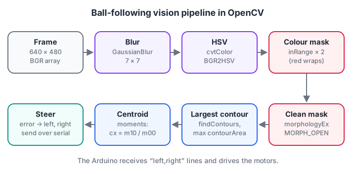
Each stage throws information away until only one useful number is left: how far the target is from the centre.
- Capture a 640 × 480 frame. Small frames process faster, and a robot rarely needs more detail.
- Blur slightly with
cv2.GaussianBlurto smooth out sensor noise. - Convert to HSV with
cv2.cvtColor. Hue says which colour, saturation how strong, value how bright. - Threshold with
cv2.inRangeto keep only pixels within the target's HSV range. - Clean the mask with a morphological opening, which deletes tiny specks.
- Find contours with
cv2.findContoursand keep the largest bycv2.contourArea. - Take the centroid from
cv2.moments:cx = m10 / m00. - Steer. Turn in proportion to
cx − width / 2, and drive forward until the blob looks large enough to mean "close".
Why HSV instead of RGB?
In RGB, a red ball in shade and the same ball in sunlight have very different numbers in all three channels. In HSV, mainly the value channel changes and the hue stays similar. That makes one HSV range work across far more lighting conditions.
Two OpenCV details catch everyone. Hue runs from 0 to 179, not 0 to 360. And red sits at both ends of that scale, so a red mask needs two ranges, roughly 0–10 and 170–179, combined with a bitwise OR.
Quick check
Why does a red colour mask in OpenCV need two inRange calls?
Hue wraps around, so red appears near 0 and near 179. Combining two ranges captures both.
Find a coloured object with numpy
Here are steps 4 and 7 on a tiny 8 × 12 image, written in plain numpy so you can see every number. The image is stored as R, G, B for readability; OpenCV frames are B, G, R.
import numpy as np
H, W = 8, 12
img = np.full((H, W, 3), (90, 110, 100), dtype=np.uint8)  # dull floor, (R, G, B)
img[2:6, 8:11] = (200, 40, 35)                             # red ball, right of centre
img[7, 0] = (185, 60, 55)                                  # one reddish speck of noise

r, g, b = (img[..., i].astype(int) for i in range(3))
mask = (r > 150) & (g < 90) & (b < 90)                    # "is this pixel red?"
print(mask.astype(int))

rows, cols = np.nonzero(mask)
cx, cy = cols.mean(), rows.mean()                          # centroid = m10/m00, m01/m00
error = (cx - (W - 1) / 2) / ((W - 1) / 2)                 # -1 = far left, +1 = far right
turn = 120 * error
print(f"pixels={mask.sum()}  centroid=({cx:.2f}, {cy:.2f})  error={error:+.2f}")
print(f"wheel speeds: left={140 + turn:.0f}  right={140 - turn:.0f}")
The ball is right of centre, so the left wheel speeds up and the robot turns right. But look closely: the true centre of the ball is column 9.0, and the single noisy pixel in the corner dragged the centroid to 8.31. On a real camera there are hundreds of such specks, which is why the next step matters.
Keep only the biggest blob
cv2.findContours groups touching pixels into separate shapes. Picking the largest one, and ignoring anything below a minimum area, removes noise and distant look-alikes. This pure-Python version does the same grouping with a flood fill:
import numpy as np
mask = np.zeros((8, 12), dtype=bool)
mask[2:6, 8:11] = True                                     # the ball: 12 pixels
mask[7, 0] = True                                          # noise speck
mask[0, 3:5] = True                                        # a red sticker on the wall

def blobs(mask):
    """Group touching True pixels (4-neighbours), like cv2.findContours."""
    seen, found = np.zeros_like(mask), []
    for start in zip(*np.nonzero(mask)):
        if seen[start]:
            continue
        stack, pixels = [start], []
        seen[start] = True
        while stack:
            y, x = stack.pop()
            pixels.append((y, x))
            for ny, nx in ((y + 1, x), (y - 1, x), (y, x + 1), (y, x - 1)):
                if 0 <= ny < mask.shape[0] and 0 <= nx < mask.shape[1] and mask[ny, nx] and not seen[ny, nx]:
                    seen[ny, nx] = True
                    stack.append((ny, nx))
        found.append(pixels)
    return found

MIN_AREA = 4
for b in sorted(blobs(mask), key=len, reverse=True):
    cx = np.mean([x for _, x in b])
    verdict = "TARGET" if len(b) >= MIN_AREA else "ignored (too small)"
    print(f"blob of {len(b):2} px, centre x = {cx:5.2f}  -> {verdict}")
Now the target's centre is exactly 9.0, and both the speck and the sticker are rejected. On a 640 × 480 frame a sensible MIN_AREA is a few hundred pixels.
Quick check
The largest contour's centroid is at x = 160 in a 640-pixel-wide frame. What should the robot do?
The centre is at 320, so the target is to the left. The error is negative and the right wheel speeds up.
Build a ball-following robot
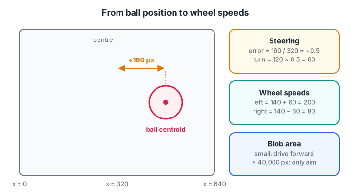
Horizontal error controls turning; blob area tells the robot how close it is.
The split of work is simple. The Raspberry Pi runs the camera and OpenCV, then sends a line such as 201,79 over USB to an Arduino, which drives an L298N or TB6612FNG exactly as in the line follower robot. Install the Python packages with sudo apt install python3-opencv python3-serial (Picamera2 is already present on the desktop image).
Raspberry Pi: vision and steering
import time
import cv2
import numpy as np
import serial
from picamera2 import Picamera2

W, H = 640, 480
RED_LOW1, RED_HIGH1 = np.array([0, 120, 70]), np.array([10, 255, 255])
RED_LOW2, RED_HIGH2 = np.array([170, 120, 70]), np.array([179, 255, 255])
BASE, TURN_GAIN, MIN_AREA, CLOSE_AREA = 140, 120, 400, 40000

arduino = serial.Serial("/dev/ttyACM0", 115200, timeout=0.1)
time.sleep(2)                                            # the Arduino resets when the port opens

picam2 = Picamera2()
picam2.configure(picam2.create_video_configuration(main={"size": (W, H), "format": "RGB888"}))
picam2.start()
kernel = np.ones((5, 5), np.uint8)

try:
    while True:
        frame = picam2.capture_array()                   # RGB888 is stored B, G, R: OpenCV-ready
        hsv = cv2.cvtColor(cv2.GaussianBlur(frame, (7, 7), 0), cv2.COLOR_BGR2HSV)
        mask = cv2.inRange(hsv, RED_LOW1, RED_HIGH1) | cv2.inRange(hsv, RED_LOW2, RED_HIGH2)
        mask = cv2.morphologyEx(mask, cv2.MORPH_OPEN, kernel)
        contours, _ = cv2.findContours(mask, cv2.RETR_EXTERNAL, cv2.CHAIN_APPROX_SIMPLE)

        left = right = 0                                 # no target: stay still
        if contours:
            c = max(contours, key=cv2.contourArea)
            area, m = cv2.contourArea(c), cv2.moments(c)
            if area > MIN_AREA and m["m00"] > 0:
                error = (m["m10"] / m["m00"] - W / 2) / (W / 2)   # -1 .. +1
                forward = BASE if area < CLOSE_AREA else 0        # close: only aim
                left = int(forward + TURN_GAIN * error)
                right = int(forward - TURN_GAIN * error)
        arduino.write(f"{left},{right}\n".encode())
finally:
    arduino.write(b"0,0\n")
    picam2.stop()
Arduino: motors with a failsafe
// Receives "left,right\n" from the Pi and drives an L298N; stops if the Pi goes quiet
const int ENA = 5, IN1 = 7, IN2 = 8, ENB = 6, IN3 = 9, IN4 = 10;
unsigned long lastCmd = 0;

void setMotor(int en, int a, int b, int s) {
  s = constrain(s, -255, 255);
  digitalWrite(a, s > 0 ? HIGH : LOW);
  digitalWrite(b, s < 0 ? HIGH : LOW);
  analogWrite(en, abs(s));
}

void setup() {
  int outs[] = {ENA, IN1, IN2, ENB, IN3, IN4};
  for (int p : outs) pinMode(p, OUTPUT);
  Serial.begin(115200);
  Serial.setTimeout(50);
}

void loop() {
  if (Serial.available()) {
    int left = Serial.parseInt();
    int right = Serial.parseInt();
    if (Serial.read() == '\n') {
      setMotor(ENA, IN1, IN2, left);
      setMotor(ENB, IN3, IN4, right);
      lastCmd = millis();
    }
  }
  if (millis() - lastCmd > 300) {        // Pi crashed or cable pulled: stop
    setMotor(ENA, IN1, IN2, 0);
    setMotor(ENB, IN3, IN4, 0);
  }
}
The turning term is a proportional controller, the same idea as in PID control explained. If the robot swings past the ball and back, lower TURN_GAIN.
Use ArUco markers for docking and position
Colour tracking breaks when the room has other red things. ArUco markers are printed black-and-white squares, each with a unique ID, which OpenCV detects reliably.
A robot can dock at a charging station marked with ID 7, or a robot arm can find exactly where a tray sits. The ArucoDetector class shown here needs OpenCV 4.7 or newer; check yours with python3 -c "import cv2; print(cv2.__version__)".
import cv2
from picamera2 import Picamera2

dictionary = cv2.aruco.getPredefinedDictionary(cv2.aruco.DICT_4X4_50)
cv2.imwrite("marker7.png", cv2.aruco.generateImageMarker(dictionary, 7, 400))  # print this

detector = cv2.aruco.ArucoDetector(dictionary, cv2.aruco.DetectorParameters())
picam2 = Picamera2()
picam2.configure(picam2.create_video_configuration(main={"size": (640, 480), "format": "RGB888"}))
picam2.start()

grey = cv2.cvtColor(picam2.capture_array(), cv2.COLOR_BGR2GRAY)
corners, ids, rejected = detector.detectMarkers(grey)
if ids is not None:
    for quad, marker_id in zip(corners, ids.flatten()):
        cx, cy = quad[0].mean(axis=0)               # centre of the four corners
        side = cv2.norm(quad[0][0] - quad[0][1])    # bigger side = closer marker
        print(f"marker {marker_id}: centre ({cx:.0f}, {cy:.0f}), side {side:.0f} px")
picam2.stop()
The marker's centre gives a steering error, just like the ball, and its side length in pixels tells you roughly how close it is.
Testing and debugging
- Check the colour range. Save one frame and print the HSV value at the ball's centre with
hsv[240, 320]. Set your range around that reading. - Look at the mask. Save
maskwithcv2.imwrite("mask.png", mask). The ball should be a solid white shape with little else. - Measure frame rate. Time 100 loops. Under about 10 frames per second the robot reacts late; shrink the frame to 320 × 240.
- Test serial on its own. Send
100,100from Python with the wheels lifted. - Test the failsafe. Stop the Python script mid-run. The Arduino must stop within 300 ms.
"Permission denied" on /dev/ttyACM0: add yourself to the dialout group and log in again. The mask is empty under tube lights: lower the saturation and value minimums. Old tutorials call cv2.CascadeClassifier: in OpenCV 5 the Haar cascade detectors moved to the contrib modules, so prefer ArUco markers or a small neural detector for new projects.
Done for the day? Try short image-logic and array quizzes on Debugshala Test.
Extensions to try next
- Camera line following. Threshold a strip at the bottom of the frame and steer by the line's centroid.
- Pick and place. Send the ball's position to the robotic arm and let inverse kinematics reach it.
- Distance from size. Calibrate blob area against measured distances and fit a curve.
- Neural detection. Swap the colour mask for a small object detector when targets have no single colour.
Key takeaways
- A beginner vision pipeline is blur, HSV, inRange, morphology, contours, centroid and steer.
- HSV is more robust to lighting than RGB; red needs two hue ranges.
- Keep only the largest blob above a minimum area to reject noise.
- Let the Pi see and decide, let the Arduino drive, and give the Arduino a failsafe.
- ArUco markers give reliable IDs and positions when colour is not enough.
FAQ
Is OpenCV good for robotics?
Yes. OpenCV is the standard open-source library for classic computer vision, with fast C++ code underneath a simple Python interface. It handles colour tracking, markers, camera calibration and feature matching, and it can run neural network models through its DNN module. It runs well on a Raspberry Pi for small frames.
Can a Raspberry Pi run OpenCV in real time?
For simple pipelines like colour tracking at 640 × 480, a Raspberry Pi 4 or 5 typically manages real-time rates suitable for a small robot. Heavier work, such as neural object detection, runs slower unless you shrink the image or add an AI accelerator. Always measure your own frame rate.
Should I learn OpenCV 4 or OpenCV 5?
Learn the current version, but do not worry about the choice. The core Python functions for images, colour conversion, thresholding, contours and ArUco markers work the same in 4.x and 5.x. The main differences for beginners are that some older modules, such as Haar cascades, moved to contrib in version 5.
How does a robot use a camera to follow a line?
It looks at a strip near the bottom of each frame, thresholds the dark line, and finds the line's centroid in that strip. The centroid's distance from the frame centre becomes the steering error, exactly as with a coloured ball. This lets the robot see curves ahead, which IR sensors cannot.
Where can I learn computer vision for robots in Indore?
Raspberry Pi with a camera for basic computer vision is part of the vision and Raspberry Pi stage of Debugshala's robotics programme at the Old Palasia campus. The course then moves on to ROS 2 basics, covered next in ROS 2 basics, and ends with a final robot project. A free demo class comes first.
From the team behind this site
Go further with the Robotics Course at Debugshala
These tutorials are written by Debugshala, a training and placement institute at Old Palasia, Indore. The classroom course adds live mentoring, real projects and interview preparation.
- Offline classes at Old Palasia, Indore
- Free demo class before you pay
- Non-IT, fresher and year-gap friendly
- Placement assistance
700+ students placed · 200+ hiring partners · 4.9★ Google rating
